2015 MERCEDES-BENZ GLE COUPE clock
[x] Cancel search: clockPage 238 of 393
Useful information
i This Owner's Manual describes all models,
series and optional equipment for your vehi-
cle that were available at the time of going to
press. National variations are possible. Note
that your vehicle may not be equipped with all
of the functions described. This is also the
case for systems and functions relevant to
safety.
i Read the information on qualified specialist
workshops: (Y page 25). Important safety notes
G
WARNING
Operating the integrated information systems and communications equipment in the vehicle
while driving will distract you from traffic con-
ditions. You could then lose control of the
vehicle. There is a risk of an accident.
Only operate these devices if road traffic con-
ditions permit. If you are unsure about the
surrounding conditions, pull over to a safe
location and make entries only while the vehi-
cle is stationary.
You must observe the legal requirements for the country in which you are currently driving whenoperating the on-board computer. G
WARNING
If the instrument cluster has failed or mal-
functioned, you may not recognise function
restrictions relevant to safety. The operating
safety of your vehicle may be impaired. There is a risk of an accident.
Drive on carefully. Have the vehicle checked
at a qualified specialist workshop immedi-
ately.
If the operating safety of your vehicle is
impaired, park the vehicle safely as soon as pos- sible. Contact a qualified specialist workshop.
The on-board computer only shows messages or warnings from certain systems in the multifunc-tion display. You should therefore make sure
your vehicle is operating safely at all times. For an overview, see the instrument cluster illus-
tration (Y page 29). Displays and operation
Instrument cluster lighting
The lighting in the instrument cluster, in the dis- plays and the controls in the vehicle interior can
be adjusted using the brightness control knob.
The brightness control knob is located on the
bottom left of the instrument cluster
(Y page 29).
X Turn the brightness control knob clockwise or
anti-clockwise.
If you turn the light switch to Ã,Tor
L, the brightness is dependent upon the
brightness of the ambient light.
i The light sensor in the instrument cluster
automatically controls the brightness of the
multifunction display.
In daylight, the displays in the instrument
cluster are not illuminated. Speedometer with segments
The speedometer is divided into segments only
on vehicles with DISTRONIC PLUS.
The segments in the speedometer indicate
which speed range is available.
R Variable SPEEDTRONIC activated
(Y page 180):
The segments light up from the start of the
scale to the selected limit speed.
R DISTRONIC PLUS activated (Y page 182):
One or two segments in the set speed range
light up.
R DISTRONIC PLUS detects a vehicle in front
moving more slowly than the stored speed:
The segments between the speed of the vehi- cle in front and the stored speed light up. Rev counter
! Do not drive in the overrevving range. Doing
so will damage the engine.
The red band in the rev counter indicates the
engine's overrevving range. Displays and operation
235On-board computer and displays Z
Page 250 of 393
X
Press the :or9 button to select the
Dipped beams Setting for:
Dipped beams Setting for: function.
You will see the selected setting: Right-
Right-
side traffic
side traffic orLeft-side traffic
Left-side traffic.
X Press the abutton to save the setting.
If you change the setting, conversion does not
take place until the next time the vehicle is
stationary.
If you set the dipped-beam headlamps for driv-
ing on the right/left, then motorway mode and
the extended range foglamps are unavailable.
These are only deactivated if the setting for driv-
ing on the left/right is set opposite to your vehi- cle's country version.
A qualified specialist workshop can set the
dipped-beam headlamps for driving on the left/
right.
Vehicle submenu Setting permanent SPEEDTRONIC
X Press the =or; button on the steering
wheel to select the Settings Settingsmenu.
X Press the :or9 button to select the
Vehicle
Vehicle submenu.
X Press ato confirm.
X Press :or9 to select the Limit
Limit
speed (winter tyres):
speed (winter tyres): function.
You will see the current setting.
X Press ato confirm.
X Press the :or9 button to adjust per-
manent SPEEDTRONIC in increments of ten
(240 km/h 240 km/h to160 km/h 160 km/h). The Off
Offsetting
switches permanent SPEEDTRONIC off.
X Press the abutton to store the entry.
For further information on permanent SPEED-
TRONIC (Y page 182).
Activating/deactivating the automatic
locking feature
If you activate the Automatic door locks
Automatic door locks
function, the vehicle is centrally locked above a
speed of approximately 15 km/h.
X Press the =or; button on the steering
wheel to select the Settings
Settings menu.
X Press the :or9 button to select the
Vehicle
Vehicle submenu.
X Press ato confirm. X
Press the :or9 button to select the
Automatic door locks
Automatic door locks function.
When the Automatic
Automatic door
doorlocks
locks function is
activated, the vehicle doors are displayed in
orange in the multifunction display.
X Press the abutton to save the setting.
For further information on the automatic locking feature; see (Y page 86).
Activating/deactivating the acoustic
locking confirmation
If you switch on the Acoustic AcousticLock
Lockfunction, an
acoustic signal sounds when you lock the vehi-
cle.
X Press the =or; button on the steering
wheel to select the Settings Settingsmenu.
X Press the :or9 button to select the
Vehicle
Vehicle submenu.
X Press ato confirm.
X Press the :or9 button to select the
Acoustic Lock
Acoustic Lock function.
If the Acoustic Lock
Acoustic Lock function is activated,
the & symbol in the multifunction display
lights up orange.
X Press the abutton to save the setting.
Heating submenu Auxiliary heating departure time
G
DANGER
If the exhaust pipe is blocked or sufficient
ventilation is not possible, toxic exhaust
fumes can enter the vehicle, especially car-
bon monoxide. This is the case, e.g. in
enclosed spaces, or if the vehicle is stuck in
snow. There is a risk of fatal injuries.
You should switch off the auxiliary heating in
enclosed spaces which do not have an extrac- tion system, e.g. a garage. If the vehicle is
stuck in snow and you must leave the auxiliary
heating running, keep the exhaust pipe and
the area around the vehicle clear of snow. To guarantee a sufficient supply of fresh air, open
a window on the side of the vehicle away from the wind. Menus and submenus
247On-board computer and displays Z
Page 324 of 393
G
WARNING
If engine oil comes into contact with hot com- ponents in the engine compartment, it may
ignite. There is a risk of fire and injury.
Make sure that engine oil does not spill out
over the filler neck. Allow the engine to cool
down and thoroughly clean the components
that have come into contact with engine oil
before you start the engine. H
Environmental note
When topping up the oil, take care not to spill
any. If oil enters the soil or waterways, it is
harmful to the environment.
! Only use engine oils and oil filters that have
been approved for vehicles with a service sys-
tem. You can obtain a list of the engine oils
and oil filters tested and approved in accord-
ance with the Mercedes-Benz Specifications
for Service Products at any Mercedes-Benz
Service Centre.
Damage to the engine or exhaust system is
caused by the following:
R using engine oils and oil filters that have not
been specifically approved for the service
system
R changing the engine oil and oil filter after
missing the change interval required by the
service system
R using engine oil additives
! Do not add too much oil. Topping up with too
much engine oil can result in damage to the
engine or to the catalytic converter. Have
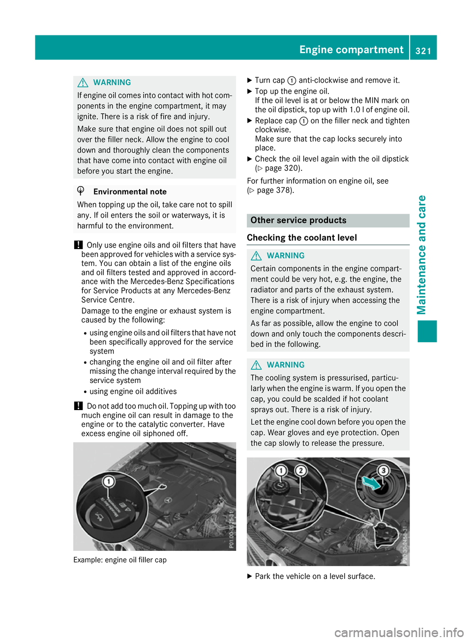
excess engine oil siphoned off. Example: engine oil filler cap X
Turn cap :anti-clockwise and remove it.
X Top up the engine oil.
If the oil level is at or below the MIN mark on
the oil dipstick, top up with 1.0 lof engine oil.
X Replace cap :on the filler neck and tighten
clockwise.
Make sure that the cap locks securely into
place.
X Check the oil level again with the oil dipstick
(Y page 320).
For further information on engine oil, see
(Y page 378). Other service products
Checking the coolant level G
WARNING
Certain components in the engine compart-
ment could be very hot, e.g. the engine, the
radiator and parts of the exhaust system.
There is a risk of injury when accessing the
engine compartment.
As far as possible, allow the engine to cool
down and only touch the components descri- bed in the following. G
WARNING
The cooling system is pressurised, particu-
larly when the engine is warm. If you open the cap, you could be scalded if hot coolant
sprays out. There is a risk of injury.
Let the engine cool down before you open the
cap. Wear gloves and eye protection. Open
the cap slowly to release the pressure. X
Park the vehicle on a level surface. Engine compartment
321Maintenance and care Z
Page 325 of 393
Only check the coolant level if the vehicle is
on a level surface and the engine has cooled
down.
X Turn the key to position 2in the ignition lock
(Y page 146).
On vehicles with KEYLESS-GO, press the
Start/Stop button twice (Y page 148).
X Check the coolant temperature gauge in the
multifunction display.
The coolant temperature must be below
70 †.
X Turn the key to position 0in the ignition lock
(Y page 146).
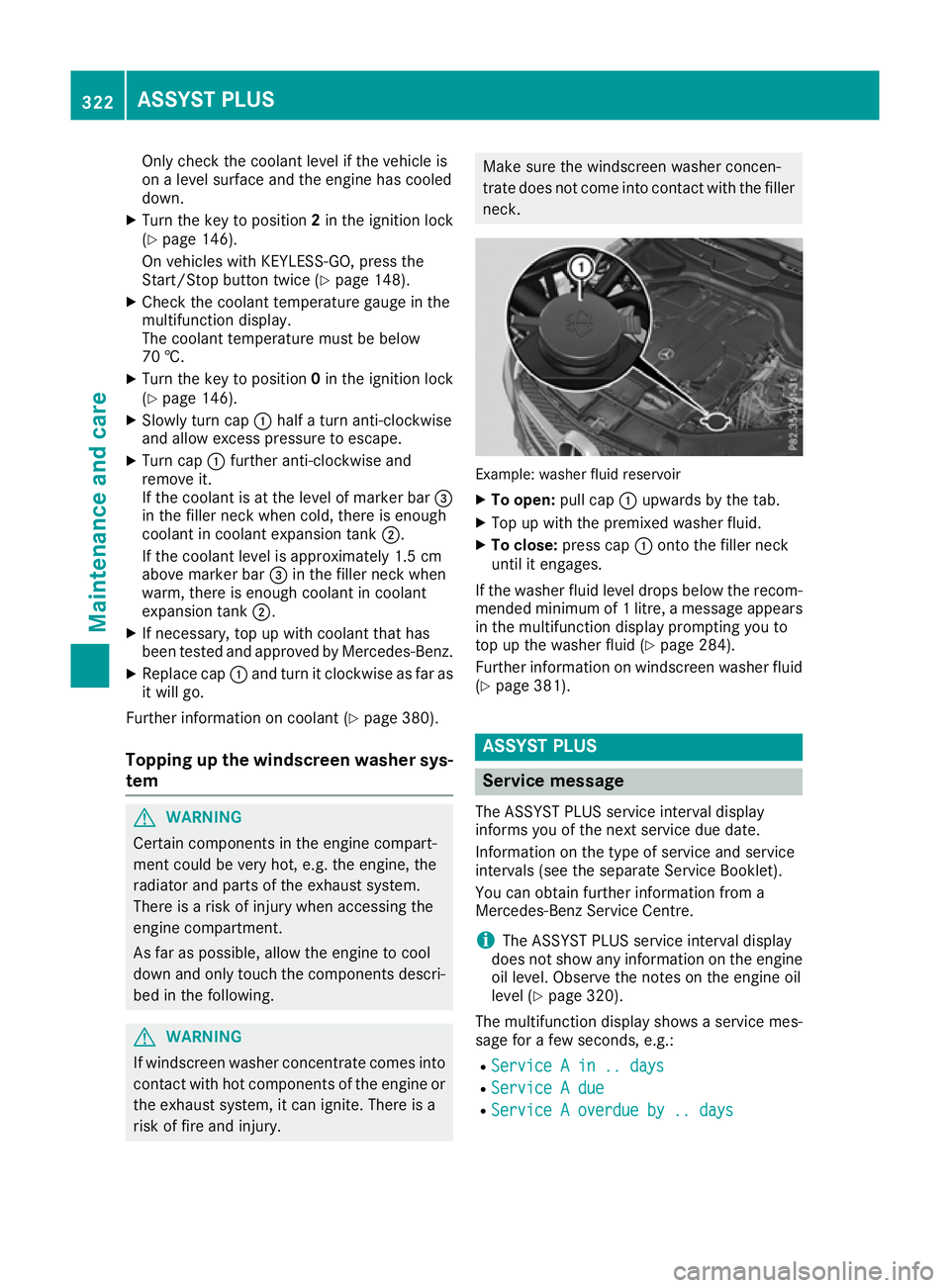
X Slowly turn cap :half a turn anti-clockwise
and allow excess pressure to escape.
X Turn cap :further anti-clockwise and
remove it.
If the coolant is at the level of marker bar =
in the filler neck when cold, there is enough
coolant in coolant expansion tank ;.
If the coolant level is approximately 1.5 cm
above marker bar =in the filler neck when
warm, there is enough coolant in coolant
expansion tank ;.
X If necessary, top up with coolant that has
been tested and approved by Mercedes-Benz.
X Replace cap :and turn it clockwise as far as
it will go.
Further information on coolant (Y page 380).
Topping up the windscreen washer sys- tem G
WARNING
Certain components in the engine compart-
ment could be very hot, e.g. the engine, the
radiator and parts of the exhaust system.
There is a risk of injury when accessing the
engine compartment.
As far as possible, allow the engine to cool
down and only touch the components descri- bed in the following. G
WARNING
If windscreen washer concentrate comes into contact with hot components of the engine or
the exhaust system, it can ignite. There is a
risk of fire and injury. Make sure the windscreen washer concen-
trate does not come into contact with the filler neck. Example: washer fluid reservoir
X To open: pull cap:upwards by the tab.
X Top up with the premixed washer fluid.
X To close: press cap :onto the filler neck
until it engages.
If the washer fluid level drops below the recom- mended minimum of 1 litre, a message appears in the multifunction display prompting you to
top up the washer fluid (Y page 284).
Further information on windscreen washer fluid
(Y page 381). ASSYST PLUS
Service message
The ASSYST PLUS service interval display
informs you of the next service due date.
Information on the type of service and service
intervals (see the separate Service Booklet).
You can obtain further information from a
Mercedes-Benz Service Centre.
i The ASSYST PLUS service interval display
does not show any information on the engine oil level. Observe the notes on the engine oil
level (Y page 320).
The multifunction display shows a service mes-
sage for a few seconds, e.g.:
R Service A in .. days
Service A in .. days
R Service A due Service A due
R Service A overdue by .. days
Service A overdue by .. days 322
ASSYST PLUSMaintenance and care
Page 342 of 393
Battery acid is caustic. Avoid contact
with the skin, eyes or clothing.
Wear suitable protective clothing, in
particular gloves, an apron and a
face mask.
Immediately rinse acid splashes off
with clean water. Consult a doctor if
necessary. Wear eye protection.
Keep children away.
Observe this Owner's Manual.
For safety reasons, Mercedes-Benz recom-
mends that you only use batteries which have
been tested and approved for your vehicle by
Mercedes-Benz. These batteries provide
increased impact protection to prevent vehicle
occupants from suffering acid burns should the battery be damaged in the event of an accident.
In order for the battery to achieve the maximum possible service life, it must always be suffi-
ciently charged.
Like other batteries, the vehicle battery may
discharge over time if you do not use the vehicle.In such cases, have the battery disconnected ata qualified specialist workshop. You can also
charge the battery with a charger recommended
by Mercedes-Benz. For more information,
please contact a qualified specialist workshop.
Have the battery charge checked more fre-
quently if you use the vehicle mainly for short
trips or if you leave it standing idle for a lengthy period. Consult a qualified specialist workshop
if you wish to leave your vehicle parked up for a
long period of time.
When you park the vehicle, remove the key if you do not require any electrical consumers. The
vehicle will then use very little energy, thus con- serving battery power.
If the power supply has been interrupted, e.g. if the battery was discharged, you will have to:
R set the clock. Information on setting the clock
can be found in the Digital Owner's Manual. On vehicles with a multimedia system and
navigation system, the clock is set automati-
cally.
R reset the function for folding the exterior mir-
rors in/out automatically, by folding the mir-
rors out once (Y page 112). Charging the 12 V battery
G
WARNING
During charging and jump-starting, explosive
gases can escape from the battery. There is a risk of an explosion.
Particularly avoid fire, naked flames, creating
sparks and smoking. Ensure there is sufficient
ventilation while charging and jump-starting.
Do not lean over a battery. G
WARNING
Battery acid is caustic. There is a risk of injury. Avoid contact with the skin, eyes or clothing.
Do not breathe in any battery gases. Do not
lean over the battery. Keep the batteries out
of the reach of children. Immediately rinse off
battery acid thoroughly with plenty of clean
water and seek medical attention at once. G
WARNING
A discharged battery can freeze at tempera-
tures below freezing point. When jump-start-
ing the vehicle or charging the battery, gases can escape from the battery. There is a risk of
an explosion.
Allow the frozen battery to thaw out before
charging it or jump-starting.
! Only use battery chargers with a maximum
charging voltage of 14.8 V.
! Only
charge the battery using the jump-start
connection point.
The jump-starting connection point is in the
engine compartment (Y page 341).
X Open the bonnet.
X Connect the battery charger in the same
order as when connecting the donor battery
during jump-starting: to the positive terminal
and earth point (Y page 341). Battery (vehicle)
339Breakdown assistance Z
Page 347 of 393
tance a distance so that the tow rope does
not sag.
R Do not use steel cables or chains to tow
your vehicle. You could otherwise damage
the vehicle.
! Do not use the trailer tow hitch for recovery
or towing. Do not use the towing eye for
recovery. This could damage the vehicle. If in doubt, have the vehicle recovered using a
crane.
! When towing, pull away slowly and
smoothly. Pull the towed vehicle as straight as possible and not at an acute angle. If the trac-
tive power is too high, the vehicles could be
damaged.
When towing, it is preferable to use a rigid tow- ing bar as opposed to a tow rope. A rigid towing
bar helps to keep the tractive power low.
! To tow vehicles with KEYLESS-GO, use the
key instead of the Start/Stop button. The
automatic transmission may otherwise
switch to position Pwhen you open the driv-
er's or front-passenger door which could
damage the transmission.
! Vehicles with differential locks: make sure
the differential locks are in automatic mode.
When towing, the differential locks must not
be switched on. The transmission may other- wise be damaged.
! You may tow the vehicle for a maximum of
50km. A towing speed of 50 km/h must not
be exceeded.
For towing distances over 50 km, the entire
vehicle must be lifted up and transported.
Observe the legal requirements for the relevant countries when towing.
It is better to have the vehicle transported than
to have it towed.
If the vehicle has suffered transmission damage, have it transported on a transporter or trailer.
The automatic transmission must be in position
N when the vehicle is being towed away.
The battery must be connected and charged.
Otherwise, you:
R cannot turn the key to position 2in the igni-
tion lock
R cannot release the electric parking brake
R cannot shift the automatic transmission to
position N Deactivate the automatic locking feature before
towing the vehicle (Y page 247). You could oth-
erwise be locked out when pushing or towing
the vehicle.
Deactivate tow-away protection before the vehi-
cle is towed away (Y page 75). Fitting/removing the towing eye
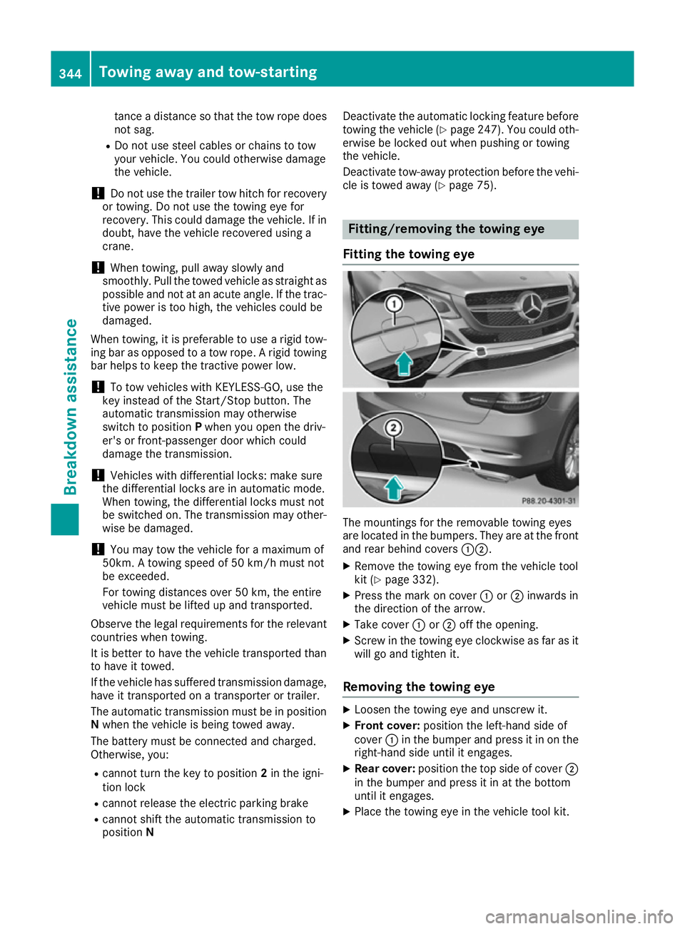
Fitting the towing eye The mountings for the removable towing eyes
are located in the bumpers. They are at the front and rear behind covers :;.
X Remove the towing eye from the vehicle tool
kit (Y page 332).
X Press the mark on cover :or; inwards in
the direction of the arrow.
X Take cover :or; off the opening.
X Screw in the towing eye clockwise as far as it
will go and tighten it.
Removing the towing eye X
Loosen the towing eye and unscrew it.
X Front cover: position the left-hand side of
cover :in the bumper and press it in on the
right-hand side until it engages.
X Rear cover: position the top side of cover ;
in the bumper and press it in at the bottom
until it engages.
X Place the towing eye in the vehicle tool kit. 344
Towing away and tow-startingBreakdown assistance
Page 371 of 393
Vehicles with tyre pressure monitor:
after
fitting an emergency spare wheel, the system
may still display the tyre pressure of the
removed wheel for a few minutes. The value
displayed for the position where the emer-
gency spare wheel is fitted is not the same as the current tyre pressure of the emergency
spare wheel. Removing/stowing the emergency
spare wheel
Vehicles with a "Minispare" emergency
spare wheel under the luggage com-
partment floor Observe the instructions and safety notes in the
"Fitting a wheel" section (Y page 357).
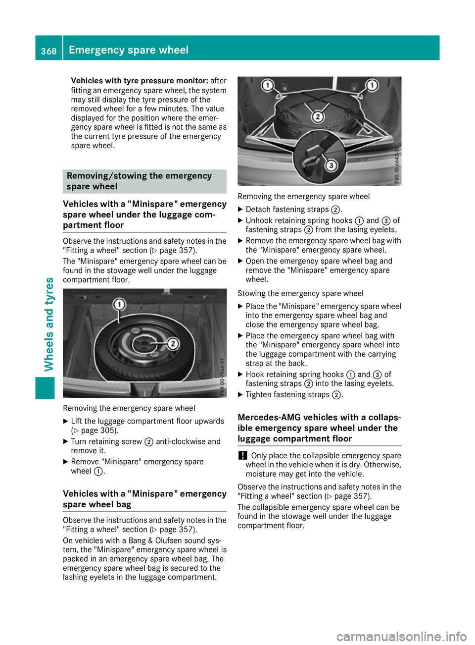
The "Minispare" emergency spare wheel can be found in the stowage well under the luggage
compartment floor. Removing the emergency spare wheel
X Lift the luggage compartment floor upwards
(Y page 305).
X Turn retaining screw ;anti-clockwise and
remove it.
X Remove "Minispare" emergency spare
wheel :.
Vehicles with a "Minispare" emergency
spare wheel bag Observe the instructions and safety notes in the
"Fitting a wheel" section (Y page 357).
On vehicles with a Bang & Olufsen sound sys-
tem, the "Minispare" emergency spare wheel is
packed in an emergency spare wheel bag. The
emergency spare wheel bag is secured to the
lashing eyelets in the luggage compartment. Removing the emergency spare wheel
X Detach fastening straps ;.
X Unhook retaining spring hooks :and =of
fastening straps ;from the lasing eyelets.
X Remove the emergency spare wheel bag with
the "Minispare" emergency spare wheel.
X Open the emergency spare wheel bag and
remove the "Minispare" emergency spare
wheel.
Stowing the emergency spare wheel
X Place the "Minispare" emergency spare wheel
into the emergency spare wheel bag and
close the emergency spare wheel bag.
X Place the emergency spare wheel bag with
the "Minispare" emergency spare wheel into
the luggage compartment with the carrying
strap at the back.
X Hook retaining spring hooks :and =of
fastening straps ;into the lasing eyelets.
X Tighten fastening straps ;.
Mercedes-AMG vehicles with a collaps-
ible emergency spare wheel under the
luggage compartment floor !
Only place the collapsible emergency spare
wheel in the vehicle when it is dry. Otherwise,
moisture may get into the vehicle.
Observe the instructions and safety notes in the
"Fitting a wheel" section (Y page 357).
The collapsible emergency spare wheel can be
found in the stowage well under the luggage
compartment floor. 368
Emergency spare wheelWheels and tyres
Page 372 of 393
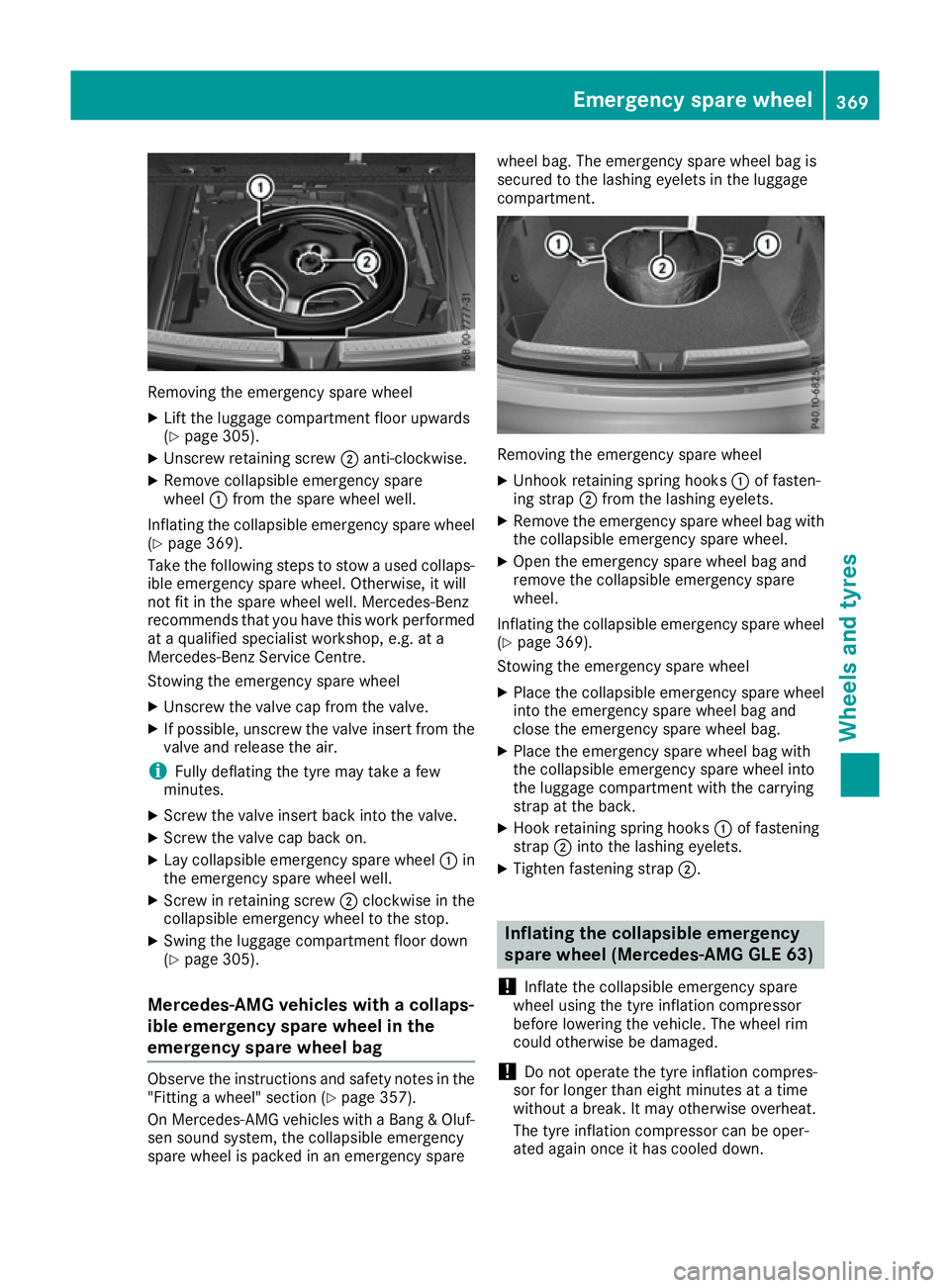
Removing the emergency spare wheel
X Lift the luggage compartment floor upwards
(Y page 305).
X Unscrew retaining screw ;anti-clockwise.
X Remove collapsible emergency spare
wheel :from the spare wheel well.
Inflating the collapsible emergency spare wheel (Y page 369).
Take the following steps to stow a used collaps-
ible emergency spare wheel. Otherwise, it will
not fit in the spare wheel well. Mercedes-Benz
recommends that you have this work performed
at a qualified specialist workshop, e.g. at a
Mercedes-Benz Service Centre.
Stowing the emergency spare wheel
X Unscrew the valve cap from the valve.
X If possible, unscrew the valve insert from the
valve and release the air.
i Fully deflating the tyre may take a few
minutes.
X Screw the valve insert back into the valve.
X Screw the valve cap back on.
X Lay collapsible emergency spare wheel :in
the emergency spare wheel well.
X Screw in retaining screw ;clockwise in the
collapsible emergency wheel to the stop.
X Swing the luggage compartment floor down
(Y page 305).
Mercedes-AMG vehicles with a collaps-
ible emergency spare wheel in the
emergency spare wheel bag Observe the instructions and safety notes in the
"Fitting a wheel" section (Y page 357).
On Mercedes-AMG vehicles with a Bang & Oluf-
sen sound system, the collapsible emergency
spare wheel is packed in an emergency spare wheel bag. The emergency spare wheel bag is
secured to the lashing eyelets in the luggage
compartment. Removing the emergency spare wheel
X Unhook retaining spring hooks :of fasten-
ing strap ;from the lashing eyelets.
X Remove the emergency spare wheel bag with
the collapsible emergency spare wheel.
X Open the emergency spare wheel bag and
remove the collapsible emergency spare
wheel.
Inflating the collapsible emergency spare wheel (Y page 369).
Stowing the emergency spare wheel
X Place the collapsible emergency spare wheel
into the emergency spare wheel bag and
close the emergency spare wheel bag.
X Place the emergency spare wheel bag with
the collapsible emergency spare wheel into
the luggage compartment with the carrying
strap at the back.
X Hook retaining spring hooks :of fastening
strap ;into the lashing eyelets.
X Tighten fastening strap ;. Inflating the collapsible emergency
spare wheel (Mercedes-AMG GLE 63)
! Inflate the collapsible emergency spare
wheel using the tyre inflation compressor
before lowering the vehicle. The wheel rim
could otherwise be damaged.
! Do not operate the tyre inflation compres-
sor for longer than eight minutes at a time
without a break. It may otherwise overheat.
The tyre inflation compressor can be oper-
ated again once it has cooled down. Emergency spare wheel
369Wheels and tyres Z