2015 MERCEDES-BENZ GLC SUV fuel
[x] Cancel search: fuelPage 32 of 497
QR code for rescue card
The QR code is secured in the fuel filler flap
and on the opposite side on the B-pillar. In the
event of an accident, rescue services can use
the QR code to quickly find the appropriate
rescue card for your vehicle. The current res- cue card contains, in a compact form, the
most important information about your vehi-
cle, e.g. the routing of the electric cables.
You can find more information under http:// portal.aftersales.i.daimler.com/public/
content/asportal/en/communication/
informationen_fuer/QRCode.html. Data stored in the vehicle
A wide range of electronic components in
your vehicle contain data memories.
These data memories temporarily or perma-
nently store technical information about:
R the vehicle's operating state
R events
R faults
In general, this technical information docu-
ments the state of a component, a module, a
system or the surroundings.
These include, for example:
R operating conditions of system compo-
nents, e.g. fluid levels
R the vehicle's status messages and those of
its individual components, e.g. number of
wheel revolutions/speed, deceleration in
movement, lateral acceleration, accelera-
tor pedal position
R malfunctions and defects in important sys-
tem components, e.g. lights, brakes
R vehicle reactions and operating conditions
in special driving situations, e.g. airbag
deployment, intervention of stability con-
trol systems
R ambient conditions, e.g. outside tempera-
ture This data is of an exclusively technical nature
and can be used to:
R assist in detecting and rectifying faults and
defects
R analyse vehicle functions, e.g. after an acci-
dent
R optimise vehicle functions
The data cannot be used to trace the vehicle's movements.
When your vehicle is serviced, technical infor-
mation can be read from the event data mem- ory and fault data memory.
Services include, for example:
R repair services
R service processes
R warranty events
R quality assurance
The vehicle is read out by employees of the
service network (including the manufacturer)
using special diagnostic testers. You can
obtain more information there, if required.
After a fault has been rectified, the informa-
tion is deleted from the fault memory or is
continually overwritten.
When operating the vehicle, situations are
conceivable in which this technical data, in
connection with other information (if neces-
sary, after consultation with an authorised
expert), could be traced to a person.
Examples include:
R accident reports
R damage to the vehicle
R witness statements
Further additional functions that have been
contractually agreed upon with the customer
allow certain vehicle data to be conveyed by
the vehicle as well. The additional functions
include, for example, vehicle location in case of an emergency. Introduction
29 Z
Page 37 of 497
Instrument cluster
Displays
i
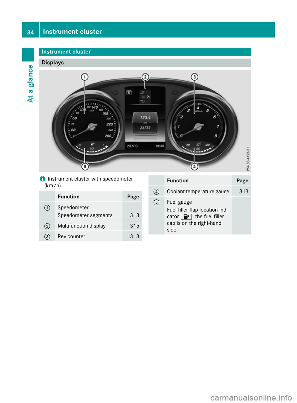
Instrument cluster with speedometer
(km/h) Function Page
:
Speedometer
Speedometer segments 313
;
Multifunction display 315
=
Rev counter 313 Function Page
?
Coolant temperature gauge 313
A
Fuel gauge
Fuel filler flap location indi-
cator 8: the fuel filler
cap is on the right-hand
side. 34
Instrument clusterAt a glance
Page 38 of 497
i
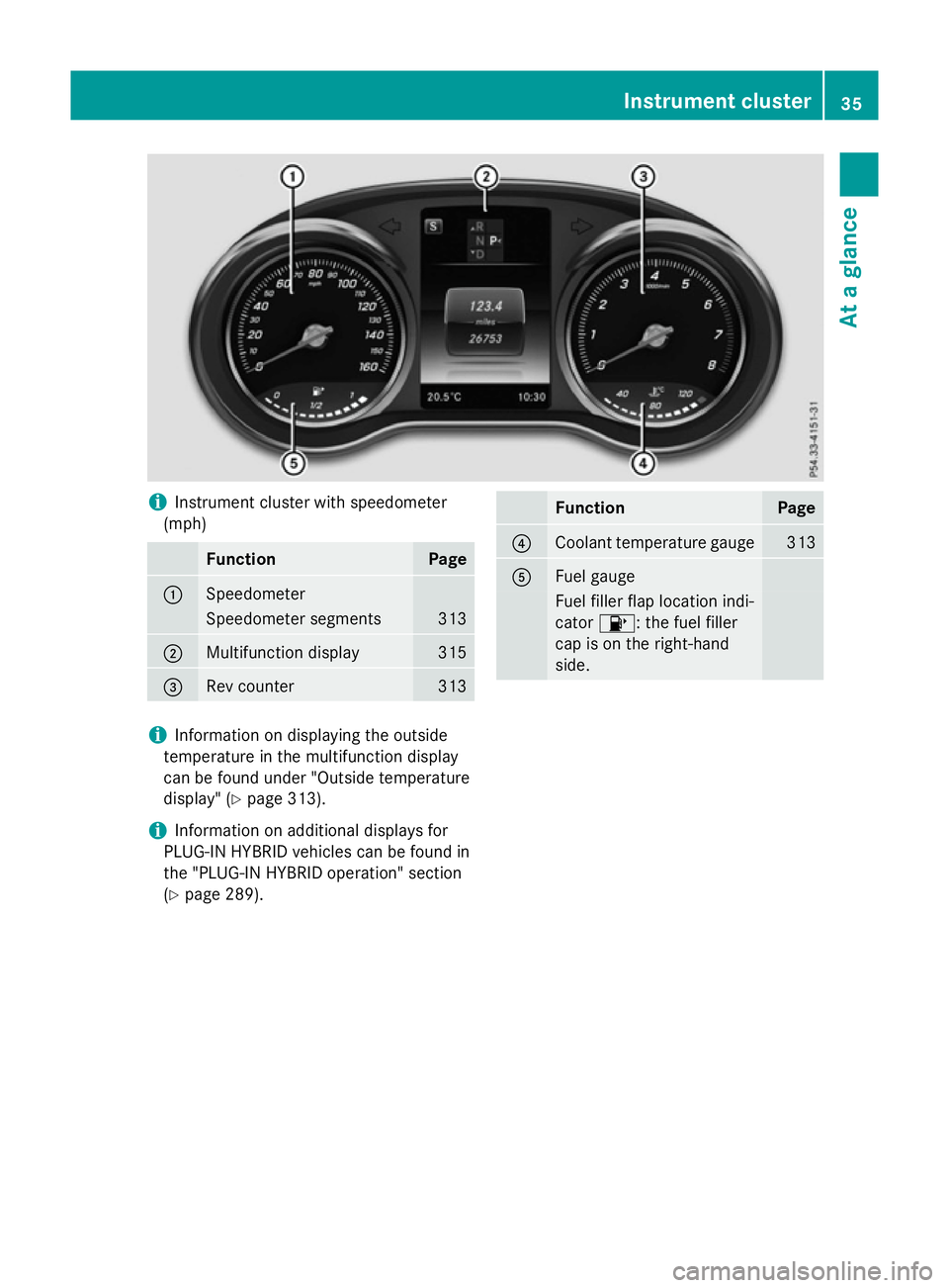
Instrument cluster with speedometer
(mph) Function Page
:
Speedometer
Speedometer segments 313
;
Multifunction display 315
=
Rev counter 313 Function Page
?
Coolant temperature gauge 313
A
Fuel gauge
Fuel filler flap location indi-
cator
8: the fuel filler
cap is on the right-hand
side. i
Information on displaying the outside
temperature in the multifunction display
can be found under "Outside temperature
display" (Y page 313).
i Information on additional displays for
PLUG-IN HYBRID vehicles can be found in
the "PLUG-IN HYBRID operation" section
(Y page 289). Instrument cluster
35At a glance
Page 39 of 497
Warning and indicator lamps
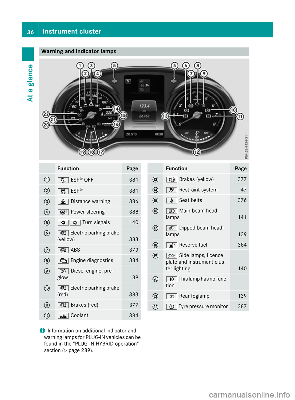
Function Page
:
å
ESP®
OFF 381
;
÷
ESP® 381
=
·
Distance warning 386
?
Ð
Power steering 388
A
#!
Turn signals 140
B
!
Electric parking brake
(yellow) 383
C
!
ABS 379
D
;
Engine diagnostics 384
E
%
Diesel engine: pre-
glow 189
F
!
Electric parking brake
(red) 383
G
J
Brakes (red) 377
H
?
Coolant 384 Function Page
I
J
Brakes (yellow) 377
J
6
Restraint system 47
K
ü
Seat belts 376
L
K
Main-beam head-
lamps 141
M
L
Dipped-beam head-
lamps 139
N
8
Reserve fuel 384
O
T
Side lamps, licence
plate and instrument clus-
ter lighting 140
P
N
This lamp has no func-
tion Q
R
Rear foglamp 139
R
h
Tyre pressure monitor 387
i
Information on additional indicator and
warning lamps for PLUG-IN vehicles can be
found in the "PLUG-IN HYBRID operation"
section (Y page 289). 36
Instrument clusterAt a glance
Page 47 of 497
Useful information
i This Owner's Manual describes all mod-
els, series and optional equipment for your
vehicle that were available at the time of
going to press. National variations are pos- sible. Note that your vehicle may not be
equipped with all of the functions descri-
bed. This is also the case for systems and
functions relevant to safety.
i Read the information on qualified special-
ist workshops: (Y page 28). Hybrid vehicles
General notes
Hybrid technology combines a fuel-efficient
internal combustion engine with a powerful
electric motor. Important safety notes
Danger of electric shock G
DANGER
The vehicle's high voltage electrical system is under high voltage. If you modify components
in the vehicle's high-voltage electrical system or touch damaged components, you may be
electrocuted. The components in the vehi-
cle's high-voltage electrical system may be
damaged in an accident, although the damage
is not visible. There is a risk of fatal injury.
Do not touch any high-voltage components
after an accident and never modify the vehi-
cle's high-voltage electrical system. Have the vehicle towed away after an accident and the vehicle's high-voltage electrical system
checked by a qualified specialist workshop.
When towing a vehicle after an accident, be
sure to observe the following sections:
R Transporting the vehicle (Y page 448)
R Towing the vehicle with both axles on the
ground (Y page 447) Read the safety instructions on towing and
tow-starting (Y
page 445). All components of the hybrid drive system are
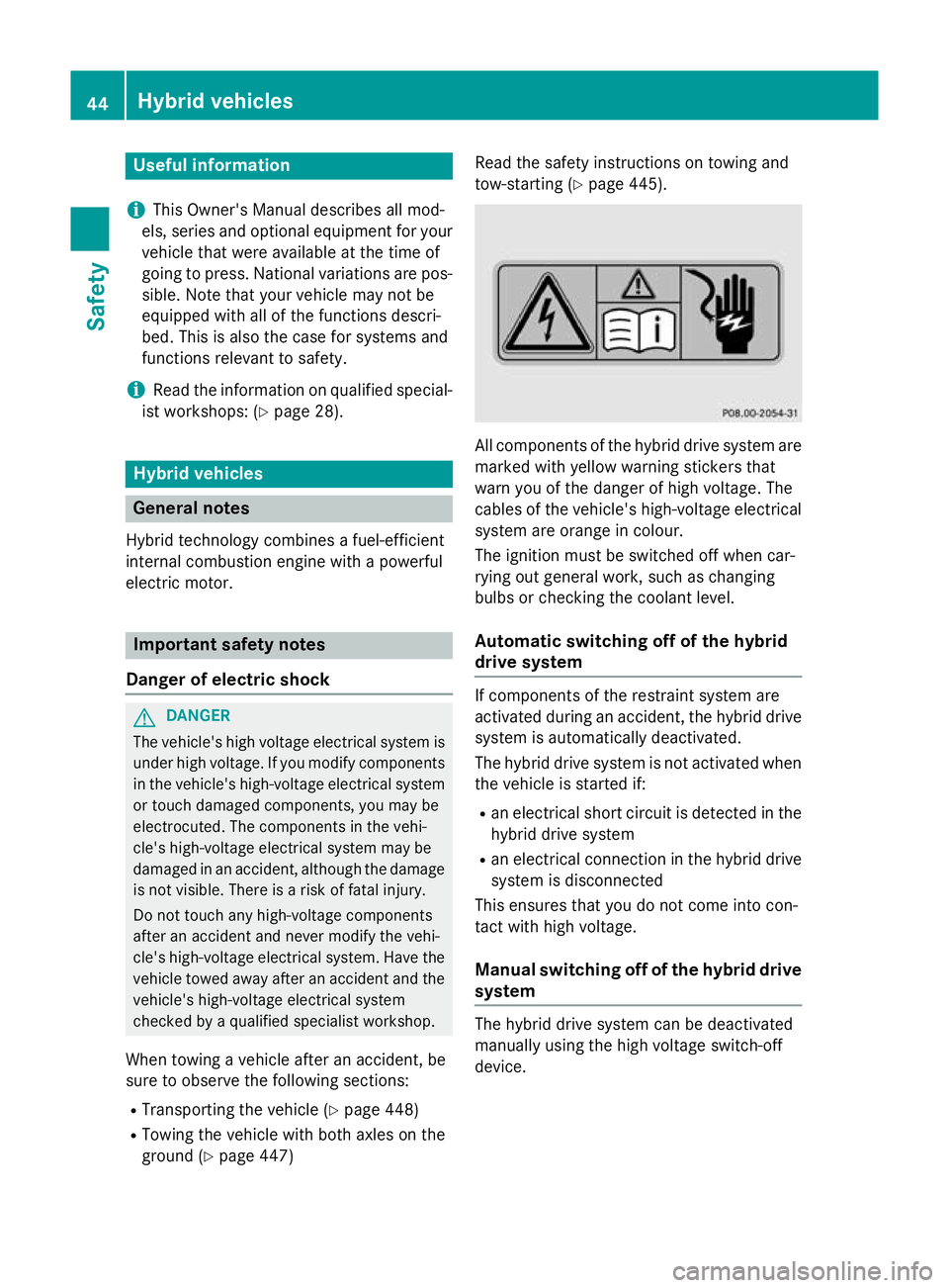
marked with yellow warning stickers that
warn you of the danger of high voltage. The
cables of the vehicle's high-voltage electrical system are orange in colour.
The ignition must be switched off when car-
rying out general work, such as changing
bulbs or checking the coolant level.
Automatic switching off of the hybrid
drive system If components of the restraint system are
activated during an accident, the hybrid drive
system is automatically deactivated.
The hybrid drive system is not activated when
the vehicle is started if:
R an electrical short circuit is detected in the
hybrid drive system
R an electrical connection in the hybrid drive
system is disconnected
This ensures that you do not come into con-
tact with high voltage.
Manual switching off of the hybrid drive system The hybrid drive system can be deactivated
manually using the high voltage switch-off
device.44
Hybrid vehiclesSafety
Page 68 of 497
PRE-SAFE
®
PLUS takes the following meas-
ures depending on the hazardous situation
detected:
R if the radar sensor system detects that a
head-on collision is imminent, the seat
belts are pre-tensioned
R if the radar sensor system detects that a
rear-end collision is imminent:
- the rear hazard warning lamps are acti-
vated and flash at a higher frequency
- the brake pressure is increased if the
driver applies the brakes when the vehi-
cle is stationary
- the seat belts are pre-tensioned
The PRE-SAFE ®
PLUS braking application is
cancelled:
R if the accelerator pedal is depressed when
a gear is engaged
R if the risk of a collision passes or is no lon-
ger detected
R if DISTRONIC PLUS indicates an intention
to pull away
If the hazardous situation passes without
resulting in an accident, the original settings
are restored. Automatic measures after an acci-
dent
Immediately after an accident, the following
measures are implemented, depending on
the type and severity of the impact:
R the hazard warning lamps are activated
R the emergency lighting is activated
R the vehicle doors are unlocked
R the front side windows are lowered
R vehicles with a memory function: the elec-
trically adjustable steering wheel is raised
R the engine is switched off and the fuel sup-
ply is cut off R
vehicles with the Mercedes-Benz emer-
gency call system: automatic emergency
call
R vehicles with the hybrid drive system: the
hybrid system and the high-voltage electri-
cal system are deactivated Children in the vehicle
Important safety notes
Accident statistics show that children
secured in the rear seats are safer than chil-
dren secured in the front-passenger seat. For this reason, Mercedes-Benz strongly advises
that you install a child restraint system on a
rear seat. Children are generally better pro-
tected there.
If a child younger than twelve years old and
under 1.50 m in height is travelling in the
vehicle:
R always secure the child in a child restraint
system suitable for Mercedes-Benz vehi-
cles. The child restraint system must be
appropriate to the age, weight and size of
the child.
R be sure to observe the instructions and
safety notes in this section in addition to
the child restraint system manufacturer's
installation instructions.
R always pay attention to the instructions
and safety notes on the automatic front-
passenger front airbag deactivation system (Y page 56). G
WARNING
If you leave children unattended in the vehi-
cle, they may be able to set the vehicle in
motion if, for example, they:
R release the parking brake
R shift the automatic transmission out of park
position P
R start the engine
In addition, they may operate vehicle equip-
ment and become trapped. There is a risk of
an accident and injury. Children in the vehicle
65Safety
Z
Page 98 of 497
ment. Otherwise, the key may not be detec-
ted, e.g. when starting the engine using the
Start/Stop button.
A check which periodically establishes a radio
connection between the vehicle and the key
determines whether a valid key is in the vehi- cle. This occurs, for example:
R when starting the engine
R whilst driving
R when the external door handles are
touched
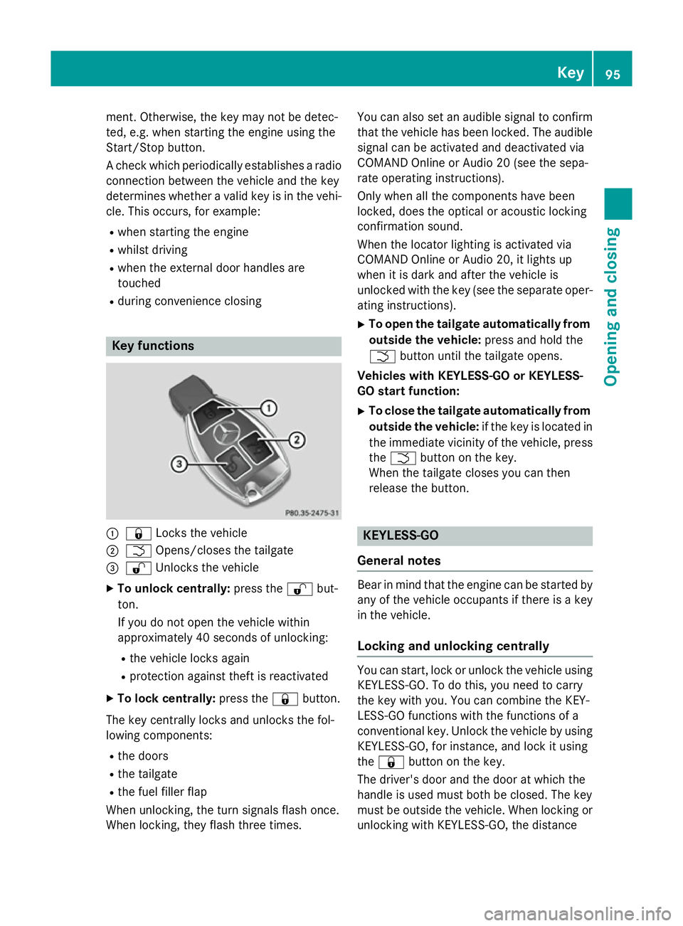
R during convenience closing Key functions
:
& Locks the vehicle
; F Opens/closes the tailgate
= % Unlocks the vehicle
X To unlock centrally: press the%but-
ton.
If you do not open the vehicle within
approximately 40 seconds of unlocking:
R the vehicle locks again
R protection against theft is reactivated
X To lock centrally: press the&button.
The key centrally locks and unlocks the fol-
lowing components:
R the doors
R the tailgate
R the fuel filler flap
When unlocking, the turn signals flash once.
When locking, they flash three times. You can also set an audible signal to confirm
that the vehicle has been locked. The audiblesignal can be activated and deactivated via
COMAND Online or Audio 20 (see the sepa-
rate operating instructions).
Only when all the components have been
locked, does the optical or acoustic locking
confirmation sound.
When the locator lighting is activated via
COMAND Online or Audio 20, it lights up
when it is dark and after the vehicle is
unlocked with the key (see the separate oper-ating instructions).
X To open the tailgate automatically from
outside the vehicle: press and hold the
F button until the tailgate opens.
Vehicles with KEYLESS-GO or KEYLESS-
GO start function:
X To close the tailgate automatically from
outside the vehicle: if the key is located in
the immediate vicinity of the vehicle, press
the F button on the key.
When the tailgate closes you can then
release the button. KEYLESS-GO
General notes Bear in mind that the engine can be started by
any of the vehicle occupants if there is a key
in the vehicle.
Locking and unlocking centrally You can start, lock or unlock the vehicle using
KEYLESS-GO. To do this, you need to carry
the key with you. You can combine the KEY-
LESS-GO functions with the functions of a
conventional key. Unlock the vehicle by using
KEYLESS-GO, for instance, and lock it using
the & button on the key.
The driver's door and the door at which the
handle is used must both be closed. The key
must be outside the vehicle. When locking or unlocking with KEYLESS-GO, the distance Key
95Opening and closing Z
Page 99 of 497
between the key and the corresponding door
handle must not be greater than 1 m.
A brief radio connection between the vehicle and the key determines whether a valid key isin, or in the direct vicinity of, the vehicle. This
occurs, for example:
R when starting the engine
R whilst driving
R when using HANDS-FREE ACCESS
R when the external door handles are
touched
R during convenience closing X
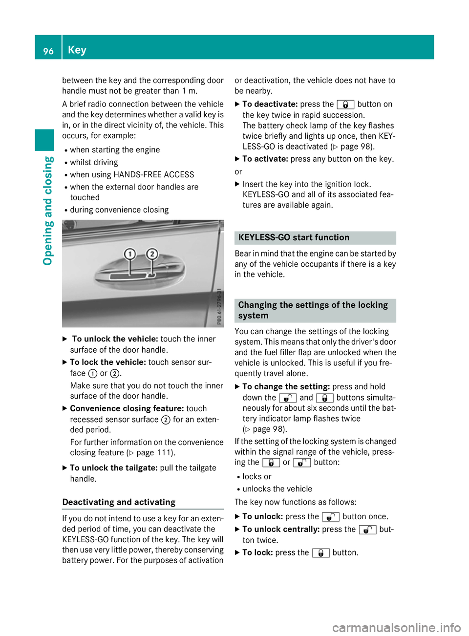
To unlock the vehicle: touch the inner
surface of the door handle.
X To lock the vehicle: touch sensor sur-
face :or;.
Make sure that you do not touch the inner
surface of the door handle.
X Convenience closing feature: touch
recessed sensor surface ;for an exten-
ded period.
For further information on the convenience closing feature (Y page 111).
X To unlock the tailgate: pull the tailgate
handle.
Deactivating and activating If you do not intend to use a key for an exten-
ded period of time, you can deactivate the
KEYLESS-GO function of the key. The key will
then use very little power, thereby conserving battery power. For the purposes of activation or deactivation, the vehicle does not have to
be nearby.
X To deactivate: press the&button on
the key twice in rapid succession.
The battery check lamp of the key flashes
twice briefly and lights up once, then KEY-
LESS-GO is deactivated (Y page 98).
X To activate: press any button on the key.
or
X Insert the key into the ignition lock.
KEYLESS-GO and all of its associated fea-
tures are available again. KEYLESS-GO start function
Bear in mind that the engine can be started by any of the vehicle occupants if there is a key
in the vehicle. Changing the settings of the locking
system
You can change the settings of the locking
system. This means that only the driver's door and the fuel filler flap are unlocked when the
vehicle is unlocked. This is useful if you fre-
quently travel alone.
X To change the setting: press and hold
down the %and& buttons simulta-
neously for about six seconds until the bat- tery indicator lamp flashes twice
(Y page 98).
If the setting of the locking system is changed
within the signal range of the vehicle, press-
ing the &or% button:
R locks or
R unlocks the vehicle
The key now functions as follows:
X To unlock: press the%button once.
X To unlock centrally: press the%but-
ton twice.
X To lock: press the &button. 96
KeyOpening and closing