2015 MERCEDES-BENZ G-CLASS SUV clock
[x] Cancel search: clockPage 80 of 274

Opening and closing the sliding sun- roof
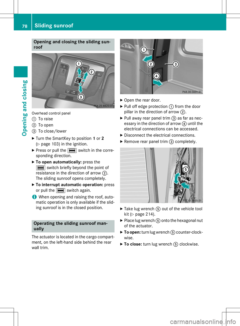
Overhead control panel :
To raise
;To open
=To close/lower
X Turn the SmartKey to position 1or 2
( Y page 103) in the ignition.
X Press or pull the ¡switch in the corre-
sponding direction.
X To open automatically: press the
¡ switch briefly beyond the point of
resistance in the direction of arrow ;.
The sliding sunroof opens completely.
X To interrupt automatic operation: press
or pull the ¡switch again.
iWhen opening and raising the roof, auto-
matic operation is only available if the slid- ing sunroof is in the closed position.
Operating the sliding sunroof man- ually
The actuator is located in the cargo compart-
ment, on the left-hand side behind the rear
wall trim.
X Open the rear door.
X Pull off edge protection :from the door
pillar in the direction of arrow ;.
X Pull away rear panel trim =as far as nec-
essary in the direction of arrow ?until the
electrical connections can be accessed.
X Disconnect the electrical connections.
X Remove rear panel trim =completely.
X
Take lug wrench Aout of the vehicle tool
kit ( Ypage 214).
X Place lug wrench Aonto the hexagonal nut
of the actuator.
X To open: turn lug wrench Acounter-clock-
wise.
X To close: turn lug wrench Aclockwise.
78Sliding sunroof
Opening and closing
Page 97 of 274

XLightly press bulb ?, turn it counter-clock-
wise and pull it out.
X Insert the new bulb and, applying slight
pressure, turn it clockwise until it engages.
X Insert the bulb holder into housing ;.
X Attach dust cover =.
X Insert housing ;.
X Replace and tighten screws :.
Windshield wipers
Switching the windshield wipers
on/off
If the wiper blades are worn, the windshield
will no longer be wiped properly. This could
prevent you from observing the traffic condi-
tions, thereby causing an accident.
Combination switch 1
$ Windshield wipers off
2ÄIntermittent wipe, low (rain sensor
set to low sensitivity)
3Å Intermittent wipe, high (rain sensor
set to high sensitivity)
4° Continuous wipe, slow
5¯Continuous wipe, fast
BíSingle wipe
CîTo wipe with washer fluid
X Switch on the ignition.
X Turn the combination switch to the corre-
sponding position.
In the ÄorÅ position, the appropriate
wiping frequency is set automatically accord-
ing to the intensity of the rain. In the Å
position, the rain sensor is more sensitive
than in the Äposition, causing the wind-
shield wipers to wipe more frequently.
Switching the rear window wiper on/ off
Combination switch :
è Switch
2bWipes with washer fluid
3ISwitches on intermittent wiping
40 Switches off intermittent wiping
5b Wipes with washer fluid
X Turn the SmartKey to position 1or 2in the
ignition lock.
X Turn switch :on the combination switch
to the corresponding position.
When the rear window wiper is switched on,
the icon appears in the instrument cluster.
iThe rear window wiper comes on auto-
matically if you shift the selector lever to R
while the windshield wiper are on.
Windshield wipers95
Lights and windshield wipers
Z
Page 111 of 274

XRemove the SmartKey from the ignition
lock.
X Turn the fuel filler cap counterclockwise
and remove it.
X Insert the fuel filler cap into the holder
bracket on the inside of filler flap ?.
Refueling
X
Completely insert the filler neck of the fuel
pump nozzle into the tank and refuel.
iDo not add any more fuel after the pump
stops filling for the first time. Otherwise,
fuel may leak out.
Closing
X Replace the fuel filler cap and turn it clock-
wise. The fuel filler cap audibly engages.
X Close the fuel filler flap.
iClose the fuel filler flap before locking the
vehicle. A locking pin otherwise prevents
the fuel filler flap from closing after the
vehicle has been locked.
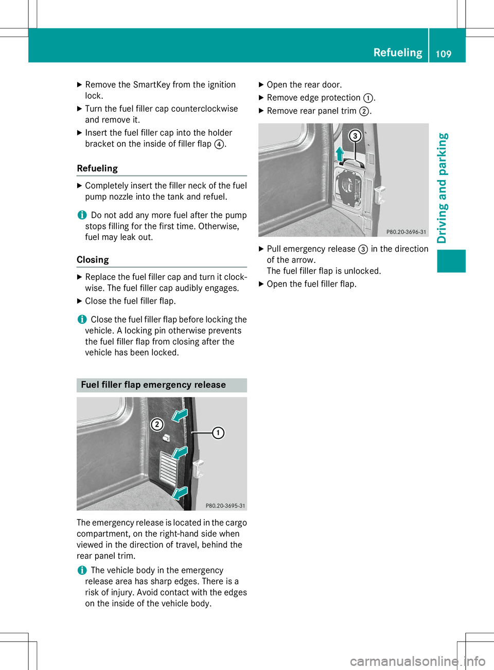
Fuel filler flap emergency release
The emergency release is located in the cargo
compartment, on the right-hand side when
viewed in the direction of travel, behind the
rear panel trim.
iThe vehicle body in the emergency
release area has sharp edges. There is a
risk of injury. Avoid contact with the edges on the inside of the vehicle body. X
Open the rear door.
X Remove edge protection :.
X Remove rear panel trim ;.
X
Pull emergency release =in the direction
of the arrow.
The fuel filler flap is unlocked.
X Open the fuel filler flap.
Refueling109
Driving and pa rking
Z
Page 182 of 274

The COMAND controller can be:R pressed briefly or pressed and held W
R turned clockwise or counter-clockwise cVd
R slid left or right XVY
R slid forwards or backwards ZVÆ
R slid diagonally aVb
Example of operation
In the instructions, operating sequences are
described as follows:
X Press the $button.
Radio mode is activated.
X Select
Radioby sliding VÆand turning
cVd the COMAND controller and press W
to confirm.
X Confirm
Station Listby pressing W.
The station list appears.
Buttons on the COMAND controller
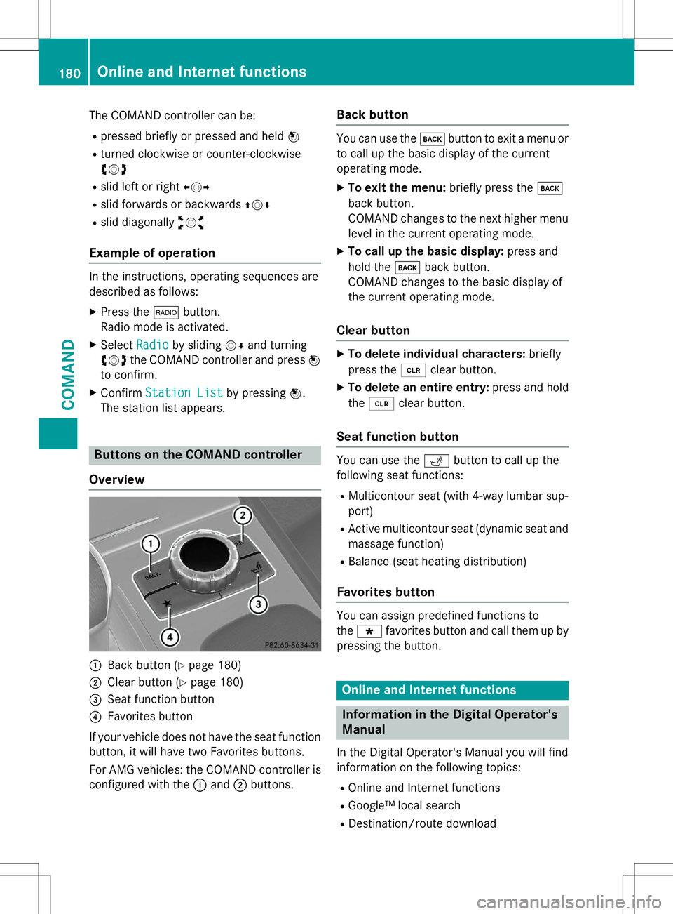
Overview
:Back button ( Ypage 180)
;Clear button ( Ypage 180)
=Seat function button
?Favorites button
If your vehicle does not have the seat function
button, it will have two Favorites buttons.
For AMG vehicles: the COMAND controller is
configured with the :and ;buttons.
Back button
You can use the kbutton to exit a menu or
to call up the basic display of the current
operating mode.
X To exit the menu: briefly press thek
back button.
COMAND changes to the next higher menu
level in the current operating mode.
X To call up the basic display: press and
hold the kback button.
COMAND changes to the basic display of
the current operating mode.
Clear button
X To delete individual characters: briefly
press the 2clear button.
X To delete an entire entry: press and hold
the 2 clear button.
Seat function button
You can use the Tbutton to call up the
following seat functions:
R Multicontour seat (with 4-way lumbar sup- port)
R Active multicontour seat (dynamic seat and
massage function)
R Balance (seat heating distribution)
Favorites button
You can assign predefined functions to the ; favorites button and call them up by
pressing the button.
Online and Internet functions
Information in the Digital Operator's
Manual
In the Digital Operator's Manual you will find
information on the following topics: R Online and Internet functions
R Google™ local search
R Destination/route download
180Online and Internet functions
COMAND
Page 209 of 274

XSwitch off the engine.
X If the engine is at normal operating tem-
perature: wait about five minutes before
carrying out the measurement.
X If the engine is not at normal operating
temperature: e.g. if the engine was only
started briefly, wait approximately
30 minutes before carrying out the meas-
urement.
iIf you wish to cancel the measurement,
press the 9or: button on the mul-
tifunction steering wheel.
Adding engine oil
GWARNING
Certain components in the engine compart-
ment, such as the engine, radiator and parts
of the exhaust system, can become very hot.
Working in the engine compartment poses a
risk of injury.
Where possible, let the engine cool down and touch only the components described in the
following.
GWARNING
If engine oil comes into contact with hot com- ponents in the engine compartment, it may
ignite. There is a risk of fire and injury.
Make sure that engine oil is not spilled next to
the filler neck. Let the engine cool down and
thoroughly clean the engine oil off the com-
ponents before starting the engine.
HEnvironmental note
When adding oil, take care not to spill any. If
oil enters the soil or waterways, it is harmful to the environment.
!Only use engine oils and oil filters that
have been approved for vehicles with a ser-
vice system. You can obtain a list of the
engine oils and oil filters tested and
approved in accordance with the
Mercedes-Benz Specifications for Service Products at any Mercedes-Benz Service
center.
Damage to the engine or exhaust system is
caused by the following:
R using engine oils and oil filters that have
not been specifically approved for the
service system
R replacing engine oil and oil filters after
the interval for replacement specified by
the service system has been exceeded
R using engine oil additives.
!Do not add too much oil. If the oil level is
above the "max" mark on the dipstick, too
much oil has been added. This can lead to
damage to the engine or the catalytic con-
verter. Have excess oil siphoned off.
Example: engine oil cap
X Turn cap :counter-clockwise and remove
it.
X Add the amount of oil required.
Observe the specifications in the on-board
computer when doing so or fill carefully to the maximum mark on the oil dipstick.
Further information on engine oil ( Y page 262).
iThe difference between the minimum
mark and the maximum mark on the oil
dipstick is approximately 2.1 US qt (2 l).
X Replac e cap:on the filler neck and
tighten clockwise.
Ensure that the cap locks into placesecurely.
Engine compartment207
Maintenance and care
Z
Page 210 of 274

Additional service products
Checking coolant level
GWARNING
Certain components in the engine compart-
ment, such as the engine, radiator and parts
of the exhaust system, can become very hot.
Working in the engine compartment poses a
risk of injury.
Where possible, let the engine cool down and touch only the components described in the
following.
GWARNING
The engine cooling system is pressurized, par-ticularly when the engine is warm. When
opening the cap, you could be scalded by hotcoolant spraying out. There is a risk of injury.
Let the engine cool down before opening the
cap. Wear eye and hand protection when
opening the cap. Open the cap slowly half a
turn to allow pressure to escape.
X Park the vehicle on a level surface.
Only check the coolant level when the vehi-
cle is on a level surface and the engine has
cooled down.
X Turn the SmartKey to position 2
( Y page 103) in the ignition lock.
X Check the coolant temperature display in
the instrument cluster.
The coolant temperature must be below
158 ‡ (70 †). X
Slow ly turn cap :half a turn counter-
clockwise and allow excess pressure to
escape.
X Turn cap :further counter-clockwise and
remove it.
If the coolant is at the level of marker bar =
in the filler neck when cold, there is enough coolant in coolant expansion tank ;.
If the coolant level is approximately 0.6 in
(1.5 cm) above marker bar =in the filler
neck when warm, there is enough coolant
in coolant expansion tank ;.
X If necessary, add coolant that has been tes-
ted and approved by Mercedes-Benz.
X Replace cap :and turn it clockwise as far
as it will go.
For further information on coolant, see( Y page 264).
Adding washer fluid to the windshield
washer system/headlamp cleaning
system
GWARNING
Certain components in the engine compart-
ment, such as the engine, radiator and parts
of the exhaust system, can become very hot.
Working in the engine compartment poses a
risk of injury.
Where possible, let the engine cool down and
touch only the components described in the
following.
GWARNING
Windshield washer concentrate could ignite if it comes into contact with hot engine compo-
nents or the exhaust system. There is a risk of
fire and injury.
Make sure that no windshield washer con-
centrate is spilled next to the filler neck.
208Engine compartment
Maintenance and care
Page 221 of 274

little energy, thus conserving battery power.
iIf the power supply has been interrupted,
e.g. due to a discharged battery, you will
have to: R set the clock. Information on setting the
clock can be found in the Digital Opera-
tor's Manual.
On vehicles with COMAND and a naviga-
tion system, the clock is set automati- cally.
R reset the head restraints on the front
seats. Information on resetting the head
restraints can be found in the Digital
Operator's Manual.
R reset the function for folding the exterior
mirrors in/out automatically, by folding
the mirrors out once ( Ypage 87).
Charging the battery
GWARNING
During charging and jump-starting, explosive
gases can escape from the battery. There is a
risk of an explosion.
Particularly avoid fire, open flames, creating
sparks and smoking. Ensure there is sufficient
ventilation while charging and jump-starting.
Do not lean over a battery.
GWARNING
Battery acid is caustic. There is a risk of injury.
Avoid contact with skin, eyes or clothing. Do
not inhale any battery gases. Do not lean over
the battery. Keep children away from batter-
ies. Wash away battery acid immediately with
plenty of clean water and seek medical atten- tion.
GWARNING
A discharged battery can freeze at tempera-
tures below freezing point. When jump-start-
ing the vehicle or charging the battery, gases can escape from the battery. There is a risk of
an explosion.
Allow the frozen battery to thaw out before
charging it or jump-starting.
!Only charge the battery using the jump-
starting connection point.
!Only use battery chargers with a maxi-
mum charging voltage of 14.8 V.
!Only charge the installed battery with a
battery charger which has been tested and
approved by Mercedes-Benz. These battery
chargers allow the battery to be charged
while still installed in the vehicle.
If, at low temperatures, the indicator lamps/
warning lamps in the instrument cluster do
not light up, it is highly likely that the dis-
charged battery has frozen. In this case you
may neither jump-start the vehicle nor charge the battery. The service life of a thawed-out
battery may be shorter. The starting charac-
teristics can be impaired, particularly at low
temperatures. Have the thawed-out battery
checked at a qualified specialist workshop.
A battery charger unit specially adapted for
Mercedes-Benz vehicles and tested and
approved by Mercedes-Benz is available as an
accessory. Contact an authorized Mercedes-
Benz Center for information and availability.
Charge the battery in accordance with the
operating instructions for the battery
charger.
The jump-starting connection point is in the
engine compartment ( Ypage 220).
X Read the operating instructions for the bat-
tery charger.
X Open the hood ( Ypage 205).
X Connect the battery charger to the positive
terminal and ground point in the same
order as when connecting the donor bat-
tery in the jump-starting procedure( Y page 220).
Battery (vehicle)219
Roadside Assistance
Z
Page 255 of 274

XTurn pressure release screw =clockwise
as far as it will go using notch ;on the
pump lever.
Pressure release screw =is closed.
iDo not turn pressure release screw =by
more than one to two revolutions. Other-
wise, hydraulic fluid could escape.
X Set jack :on solid ground.
X Position jack :on the axle carrier tube ;
of the front or rear axle. Jack :must
always stand vertically, even on slopes.
Make sure that jack :is correctly posi-
tioned under axle carrier tube ;. The front
or rear axle must sit securely in the recess of jack :.
X Raise the vehicle by pumping in the direc-
tion of the arrow until the tire is 1.2 in
(3 cm) off the ground at the most.
Removing a wheel
!Do not place wheel bolts in sand or on a
dirty surface. The bolt and wheel hub
threads could otherwise be damaged when you screw them in.
X Unscrew the wheel bolts.
X Remove the wheel.
Mounting a new wheel
GWARNING
Oiled or greased wheel bolts/wheel nuts and
damaged wheel bolt/wheel nut/wheel hub
threads can cause wheel bolts/wheel nuts to come loose. As a result, you could lose a
wheel while driving. There is a risk of an acci- dent.
Never oil or grease wheel bolts/wheel nuts. In the event of damage to the threads, contact a
qualified specialist workshop immediately.
Have the damaged wheel bolts/wheel nuts or hub threads replaced/renewed. Do not con-
tinue driving.
GWARNING
If you tighten the wheel bolts or wheel nuts
when the vehicle is raised, the jack could tip
over. There is a risk of injury.
Only tighten the wheel bolts or wheel nuts
when the vehicle is on the ground.
!To prevent damage to the paintwork, hold
the wheel securely against the wheel hub
while screwing in the first wheel bolt.
Always pay attention to the instructions and
safety notes in the "Changing a wheel" sec-
tion ( Ypage 250).
X Clean the wheel and wheel hub contactsurfaces.
X Place the new wheel on the wheel hub and
push it on.
X Tighten the wheel bolts until they are fin-
ger-tight.
Lowering the vehicle
GWARNING
The wheels could work loose if the wheel nuts
and bolts are not tightened to the specified
tightening torque. There is a risk of accident.
Have the tightening torque immediately
checked at a qualified specialist workshop
after a wheel is changed.
Changing a wheel253
Wheels and tires
Z