2015 MERCEDES-BENZ E-CLASS SALOON buttons
[x] Cancel search: buttonsPage 174 of 497
X
Briefly press the ubutton.
X Press the ,or. button repeatedly
unti lthe time to be changed appears in the
display.
X Press the uand^ buttons simulta-
neously.
The Îsymbo linthe remote control dis-
play flashes.
X Press the ,or. button to set the
desire ddeparture time.
i The longer yo
upress the ,or.
button, the faster the time changes.
X Press the uand^ button simulta-
neously.
The new departure time is stored.
Activating the se tdeparture time
X Briefly press the ubutton.
X Press the ,or. button repeatedly
unti lthe desire ddeparture time appears in
the display.
X Press the ubutton.
The Ísymbol, the departure time and,
depending on the selected departure time, the letter A, BorCappea rinthe display.
Deactivatin gthe se tdeparture time
X Briefly press the ubutton.
The statu softhe auxiliary heating is shown
in the display.
X Press the .button.
The firs tdeparture time store dappears in
the display.
X Press the ^button.
OFF
OFF is shown in the remote control display.
Replacing the remote control battery Important safety notes
G
WARNING
Batterie scontai ntoxic and corrosiv esubstan-
ces. If batterie sare swallowed, it can result in
severe health problems. There is ariskoff atal
injury. Kee
pbatterie soutof the reach of children. If
ab attery is swallowed, see kmedica lattention
immediately. H
Environmental note Batterie
scontai npollutants.
It is illega ltodispose of them
with the household rubbish.
The ym ustb ec ollected sep-
arately and disposed of in an environmentally responsible
recycling system. Dispose of batterie
sinan
environmentally responsible
manner. Take discharged
batterie stoaqualified spe-
cialist worksho portoacol-
lection point for used batter-
ies.
Replacing the battery If the battery need
stobereplaced, the bat-
tery symbo lonthe left of the display is shown
as empty. ACR2450 lithiu mbattery is
required whe nreplacing the battery.
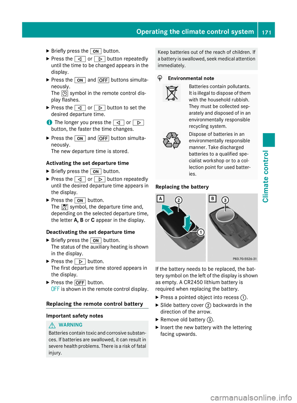
X Press apointed object into recess :.
X Slide battery cover ;backwards in the
direction of the arrow.
X Remove old battery =.
X Inser tthe new battery with the lettering
facing upwards. Operating the climate control system
171Climate control Z
Page 297 of 497
In the
Heating
Heating submenu, you can select a
stored departure time or change adeparture
time.
The auxiliary heating timer function calcu-
lates the switch-on time according to the out-
side temperature so that the vehicle is pre-
heated by the departure time. When the
departure time is reached ,the auxiliary heat-
ing continues to heat for afurther five
minutes and then switches off. The auxiliary
heating adopts the THERMATIC or
THERMOTRONIC temperature setting.
You can switch off the auxiliary heating by
using the remote control or the auxiliary heat- ing button on the centre console.
i Switch the auxiliary heating on regularly
once amonth for aboutt en minutes.
Further information on auxiliary heating
(Y page 168).
Selecting the departur etime or deactivat-
ing aselected departur etime
X Press the =or; button on the steer-
ing wheeltos elect theSettings
Settings menu.
X Press the :or9 button to select the
Heating
Heating submenu.
X Press ato confirm.
You wills ee the selected setting.
X Press ato confirm.
X Press the :or9 button to select
one of the three departure times or Timer Timer
off
off (no timer active).
X Press ato confirm.
If ad eparture time is selected, the yellow
indicator lamp lights up on the auxiliary
heating button.
Changing the departur etime
X Press the =or; button on the steer-
ing wheeltos elect theSettings Settings menu.
X Press the :or9 button to select the
Heating
Heating submenu.
X Press ato confirm.
You wills ee the selected setting. X
Press the :or9 button to select A A,B B
or Change C
Change C.
X Press ato confirm.
You can now change the departure time.
X Press the =or; button to select the
display to be changed: hours, minutes.
X Press the :or9 button to set the
selected display.
X Press the abutton to store the entry.
The yellow indicator lamp on the auxiliary
heating button lights up.
Comfort Activating/deactivating the EASY-
ENTRY/EXIT feature
G
WARNING
When the EASY-ENTRY/EXIT feature adjusts
the steering wheel, you and other vehicle
occupants –particularly childre n–could
become trapped .There is arisk of injury.
Whilet he EASY-ENTRY/EXIT feature is mak-
ing adjustments, make sure that no one has
any body parts in the sweep of the steering
wheel.
If someone is trapped:
R press one of the memory function position
buttons, or
R move the switch for steering wheela djust-
ment in the opposite direction to that in
which the steering wheelism oving.
The adjustment process is stopped.
X Press the =or; button on the steer-
ing wheeltos elect theSettings Settings menu.
X Press the :or9 button to select the
Convenience
Convenience submenu.
X Press ato confirm.
X Press the :or9 button to select the
Easy Entry/Exit:
Easy Entry/Exit: function.
If the Easy Entry/Exit
Easy Entry/Exit function is activa-
ted, the vehicle steering wheelisd isplayed
in orange in the multifunction display.
X Press the abutton to save the setting. 294
Menus and submenusOn-board computer and displays
Page 371 of 497
More information on suitable mobile phones,
mobile phone brackets and on connecting
Bluetooth ®
-capable mobile phones to
COMAND Online/Audio 20 can be obtained:
R at your Mercedes-Ben zService Centre
R on the Internet at http://www.mercedes-
benz.com/connect
The functions and services available when
you use the phone depend on your mobile
phone model and service provider.
Using amobile phone To connect
amobile phone to the exterior
aerial and charge it, insert it into the mobile
phone bracket.
X Open the telephone compartment
(Y page 344).
X Place the mobile phone bracket into the
pre-installed fitting; see the separate instal-
lation instructions for the mobile phone fit-
ting.
X Insert the mobile phone into the mobile
phone bracket; see the separate installa-
tion instructions for the mobile phone fit-
ting.
i The mobile phone can also be operated
without being in the bracket. However, the charging function and aerial function are
not available.
In order to use Bluetooth ®
(SAP profile) on
your telephone module, you must first insert
the telephone module into the pre-installed
fitting. This connects it to the exterior aerial.
If you wish to charge the mobile phone, then
you must connect it to aUSB port.
Further information on the telephone module
with Bluetooth ®
(SAP profile) can be found in
the Digital Owner's Manual.
Operating the mobile phone You can operate the telephone using the
6 and~ buttons on the multifunction
steering wheel. You can operate other mobile phone functions via the on-board computer
(Y page 284).
When you remove the key from the ignition
lock, the mobile phone is disconnected from
the hands-free system. Active calls will first
be transferred to the mobile phone directly.
Mobile phone bracket in the stowage
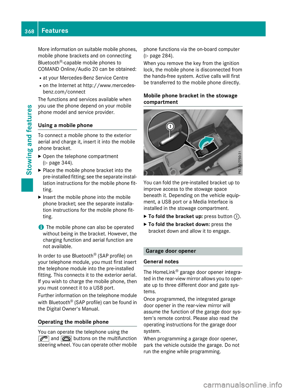
compartment You can fold the pre-installed bracket up to
improve access to the stowage space
beneath it. Depending on the vehicle equip-
ment,aU
SB port or aMedia Interface is
installed in the stowage compartment.
X To fold the bracket up: press button:.
X To fold the bracket down: press the
bracket down and allow it to engage. Garage door opener
General notes The HomeLink
®
garage door opener integra-
ted in the rear-view mirror allowsy ou to oper-
ate up to three different door and gate sys-
tems.
Once programmed, the integrated garage
door opener in the rear-view mirror will
assume the function of the garage door sys-
tem's remote control. Please also read the
operating instructions for the garage door
system.
When programming agarage door opener,
park the vehicle outside the garage. Do not
run the engine while programming. 368
FeaturesStowing and features
Page 372 of 497
The garage door opener is only available for
certain countries. Observe the legal require-
mentsf or each individual country.
The HomeLink ®
garage door opener is com-
patible with most European garage and gate
opener drives. More information on Home-
Link ®
and/or compatible products is availa-
ble:
R at aq ualified specialist workshop
R via the HomeLink ®
Hotline
(0) 080004 66 354 65 or alternatively
+49 (0) 6838 907-277
R on the Internet at http://
www.homelink.com
Important safety notes G
WARNING
When you operate or program the garage door with the integrated garage door opener, per-
sons in the range of movemen tofthe garage
door can become trapped or struck by the
garage door. There is arisk of injury.
When using the integrated garage door
opener, alway smake sure that nobody is
within the range of movemen tofthe garage
door. G
WARNING
Combustion engines emit poisonous exhaust
gases such as carbon monoxide. Inhaling
these exhaust gases leads to poisoning. There is ar isk of fatal injury. Therefore never leave
the engine runnin ginenclosed spaces with-
out sufficient ventilation.
Programming Programming buttons
Pay attention to the "Importan
tsafety notes"
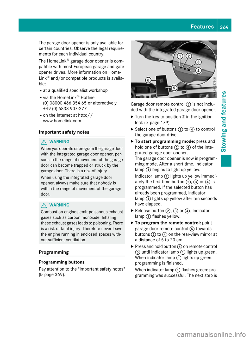
(Y page 369). Garage door remot
econtrol Ais not inclu-
ded with the integrated garage door opener.
X Turn the key to position 2in the ignition
lock (Y page 179).
X Select one of buttons ;to? to control
the garage door drive.
X To startp rogramming mode: press and
hold one of buttons ;to? of the inte-
grated garage door opener.
The garage door opener is now in program- ming mode. After ashort time, indicator
lamp :begins to light up yellow.
Indicator lamp :lights up yellow immedi-
ately the first time button ;,=or? is
programmed. If the selected button has
already been programmed, indicator
lamp :lights up yellow after ten seconds
have elapsed.
X Release button ;,=or?.I ndicator
lamp :flashes yellow.
X To program the remot econtrol: point
garage door remot econtrol Atowards
buttons ;to? on the rear-view mirror at
ad istanc eof5to20c m.
X Press and hold button Bon remot econtrol
A until indicator lamp :lights up green.
When indicator lamp :lights up green:
programming is finished.
When indicator lamp :flashes green: pro-
gramming was successful. The next step is Features
369Stowing and features Z
Page 374 of 497
Opening or closing the garage door
Oncep
rogrammed, the integrated garage
door opener will assume the function of the
garage door system's remot econtrol. Please
also read the operatin ginstructions for the
garage door system.
X Turn the key to position 2in the ignition
lock (Y page 179).
X Press button ;,=or? which you have
programmed to operate the garage door.
Garage door system with afixed code: indi-
cator lamp :lights up green.
Garage door system with arolling code:
indicator lamp :flashes green.
The transmitter will transmit asignal for as
long as the button is pressed. The trans-
mission is halted after amaximum of ten
seconds and indicator lamp :lights up
yellow.
X Press button ;,=or? again if neces-
sary.
Clearing the memory Make sure that you clear the memory of the
integrated garage door opener before selling
the vehicle.
X Turn the key to position 2in the ignition
lock (Y page 179).
X Press and hold buttons ;and ?.
The indicator lamp initially lights up yellow
and then green.
X Release buttons ;and ?.
The memory of the integrated garage door
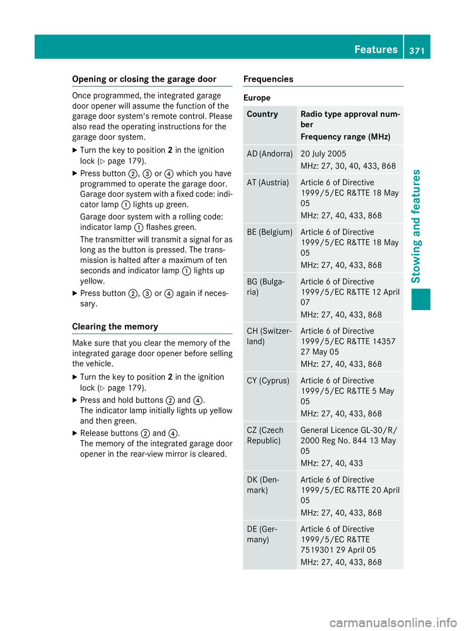
opener in the rear-view mirror is cleared. Frequencies Europe
Country Radio typea
pproval num-
ber
Frequency range (MHz) AD (Andorra) 20 July 2005
MHz:2
7, 30, 40, 433,8 68 AT (Austria) Article
6ofDirective
1999/5/ECR &TTE 18 May
05
MHz:2 7, 40, 433,8 68 BE (Belgium) Article
6ofDirective
1999/5/ECR &TTE 18 May
05
MHz:2 7, 40, 433,8 68 BG (Bulga-
ria) Article
6ofDirective
1999/5/ECR &TTE 12 April
07
MHz:2 7, 40, 433,8 68 CH (Switzer-
land) Article
6ofDirective
1999/5/ECR &TTE 14357
27 May 05
MHz:2 7, 40, 433,8 68 CY (Cyprus) Article
6ofDirective
1999/5/ECR &TTE5May
05
MHz:2 7, 40, 433,8 68 CZ (Czech
Republic) General Licence GL-30/R/
2000R
eg No. 844 13 May
05
MHz:2 7, 40, 433 DK (Den-
mark) Article
6ofDirective
1999/5/ECR &TTE 20 April
05
MHz:2 7, 40, 433,8 68 DE (Ger-
many) Article
6ofDirective
1999/5/ECR &TTE
751930129A pril 05
MHz:2 7, 40, 433,8 68 Features
371Stowing and features Z