2015 MERCEDES-BENZ E-CLASS COUPE garage door opener
[x] Cancel search: garage door openerPage 13 of 345

Warning lamp (engine diagnos-
tics) ............................................... 252
Engine electronics
Notes ............................................. 327
Problem (fault) ...............................1 38
Engine jump starting
see Jump starting (engine)
Engine oil
Additives ........................................ 333
Checking the oil level ..................... 285
Checking the oil level using the
dipstick .......................................... 285
Display message ............................ 232
Filling capacity ............................... 333
Notes about oil grades ................... 332
Notes on oil level/consumption .... 285
Topping up ..................................... 286
Entering an address
See also Digital Owner's Manual ... 256
Environmental protection
Returning an end-of-life vehicle ....... 23
ESP ®
(Electronic Stability Pro-
gram)
Characteristics ................................. 67
Deactivating/activating ................. 214
Deactivating/activating (notes) ....... 68
Display message ............................ 223
Function/notes ................................ 67
General notes .................................. 67
Important safety guidelines ............. 67
Trailer stabilisatio n.......................... 68
Warning lamp ................................. 249
ETS/4ETS (Electronic Traction Sys-
tem) ...................................................... 67
Exhaust pipe (cleaning instruc-
tions) .................................................. 293
Exterior lighting
Settings options ............................. 106
see Lights
Exterior mirrors
Adjusting ....................................... 102
Anti-dazzle mode (automatic) ........ 103
Folding in when locking (on-boardcomputer) ...................................... 220
Folding in/out (automatically )....... 103
Folding in/out (electrically) ........... 103
Out of position (troubleshooting) ... 103 Parking position ............................. 104
Resetting ....................................... 103
Storing settings (memory func-
tion) ............................................... 104 F
Fault message see Display messages
Favourites
Overview ........................................ 257
Filler cap
see Fuel filler flap
Fire extinguisher ............................... 296
First-aid kit ......................................... 296
Fitting a wheel
Fitting a wheel ............................... 324
Lowering the vehicle ...................... 324
Preparing the vehicle ..................... 321
Raising the vehicl e......................... 322
Removing a whee l.......................... 323
Securing the vehicle against roll-
ing away ........................................ 322
Flat tyre
MOExtended tyre s......................... 298
Preparing the vehicle ..................... 298
TIREFIT kit ...................................... 299
see Emergency spare wheel
Floormat ............................................. 281
Foglamps
Extended rang e.............................. 109
Frequencies
Garage door opener ....................... 279
Mobile phone ................................. 327
Two-way radio ................................ 327
Fuel
Additives ........................................ 331
Consumption statistics .................. 209
Displaying the current consump-
tion ................................................ 209
Displaying the range ...................... 209
Fuel gaug e....................................... 30
Grade (petrol) ................................ 330
Important safety notes .................. 330
Notes for E 200, E 250, E400 ........ 331
Problem (malfunction) ................... 150
Quality (diesel )............................... 331
Refuelling ....................................... 147 10
Index
Page 14 of 345

Tank content/reserve fuel .............3
30
Fuel filler flap
Opening ......................................... 148
Fuel filter (white display message) .. 233
Fuel level
Calling up the range (on-board
computer) ...................................... 209
Gauge .............................................. 30
Fuel reserve
see Fuel
Fuel tank
Capacity ........................................ 330
Problem (malfunction) ................... 150
Fuse allocation chart (vehicle tool
kit) ...................................................... 297
Fuses
Allocation chart ............................ .311
Before changing ............................ .311
Dashboard fuse box ....................... 311
Fuse box in the boot ..................... .312
Fuse box in the engine compart-
ment .............................................. 311
Important safety notes .................. 310 G
Garage door opener Clearing the memory ..................... 278
Frequencies ................................... 279
General notes ................................ 276
Important safety notes .................. 277
Opening/closing the garage door .. 278
Problems when programming ....... .278
Programming (button in the rear-
view mirror) ................................... 277
Synchronising the rolling code ....... 278
Genuine Mercedes-Benz parts ........... 23
Glove compartment .......................... 266
Google™ Local Search
See also Digital Owner's Manual ... 256 H
Hazard warning lamps ......................108
Head restraints
Adjusting ......................................... 95
Adjusting (electrically) ..................... 96
Adjusting (manually) ........................ 95 see NECK-PRO head restraints
Headbag
Display message ............................ 229
Headlamp flasher .............................. 108
Headlamps
Misting up ...................................... 110
see Automatic headlamp mode
Heating
see Climate control
High-pressure cleaners .................... 291
Hill start assist .................................. 135
HOLD function
Activating ....................................... 171
Deactivating ................................... 171
Display message ............................ 234
Function/notes ............................ .170
Home address
See also Digital Owner's Manual ... 256
Horn ...................................................... 28 I
Ignition lock see Key positions
Immobiliser .......................................... 71
Indicator and warning lamp
Restraint system ............................ 251
Indicator and warning lamps
COLLISION PREVENTION ASSIST
PLUS .............................................. 254
Coolant .......................................... 252
Engine diagnostics ......................... 252
Indicator lamps
Display message ............................ 229
see Warning and indicator lamps
Indicators
see Turn signals
Insect protection on the radiator .... 285
Instrument cluster
Overview .......................................... 30
Settings ......................................... 216
Warning and indicator lamps ........... 30
Instrument cluster lighting .............. 216
Intelligent Light System
Activating/deactivating ................. 217
Display message ............................ 229
Overview ........................................ 108 Index
11
Page 19 of 345

R
Radiator cover ................................... 285
Radio
Selecting a station ......................... 211
see separate operating instructions
Radio mode
See also Digital Owner's Manua l... 256
Radio-based vehicle components
Declaration of conformity ................ 25
Rain closing feature
Panorama sliding sunroo f................ 89
Reading lamp ..................................... 110
Rear compartment
Setting the temperature ................ 120
Rear foglamp
Display message ............................ 229
Switching on/of f........................... 107
Rear seat
Display message ............................ 243
Rear window blind ............................ 273
Rear window heating
Problem (fault) ............................... 123
Switching on/of f........................... 122
Rear-compartment seat belt sta-
tus indicator ........................................ 41
Rear-view mirror
Anti-dazzle mode (automatic) ........ 103
Dipping (manual) ........................... 102
Refuelling
Fuel gaug e....................................... 30
Important safety notes .................. 147
Refuelling process ......................... 148
see Fuel
Remote control
Auxiliary heating/ventilation .......... 125
Changing the batteries (auxiliary
heating) ......................................... 127
Garage door opener ....................... 276
Programming (garage door
opener) .......................................... 277
Replacing bulbs
Important safety notes .................. 111
Overview of bulb types .................. 111
Replacing the battery (auxiliary
heating remote control) .................... 127
Rescue card ......................................... 26 Reserve (fuel tank)
see Fuel
Reserve fuel
Display message ............................ 232
Warning lamp ................................. 252
Residual heat (climate control) ........ 124
Restraint system
Display message ............................ 228
Introduction ..................................... 36
Problem (malfunction) ................... 251
Warning lamp (function) ................... 37
Rev counter ........................................ 206
Reverse gear
Engaging (manual transmission) .... 139
Reversing camera
Cleaning instructions ..................... 293
Display in the multimedia system .. 182
Function/note s............................. 181
Switching on/of f........................... 181
Reversing feature
Panorama sliding sunroo f................ 89
Roller sunblind s............................... 90
Side windows ................................... 85
Sliding sunroof ................................. 89
Reversing lamp (display message) .. 229
Roller sunblind
Panorama sliding sunroo f................ 90
Rear window .................................. 273
Roof lining and carpets (cleaning
instructions) ...................................... 295
Roof load (maximum) ........................ 335
Route guidance
See also Digital Owner's Manua l... 256 S
Safety Children in the vehicle ..................... 47
see Occupant safety
Safety system
see Driving safety systems
SD memory card
Ejecting .......................................... 263
Inserting ........................................ 263
Inserting/removing ........................ 263
See also Digital Owner's Manua l... 256
Selecting ........................................ 211 16
Index
Page 37 of 345

Overhead control panel
Function Page
:
u
Switches the rear inte-
rior lighting on/off 110
;
|
Switches the automatic
interior lighting control
on/off 110
=
p
Switches the right-
hand reading lamp on/off 110
?
ë
Deactivates tow-away
protection 72
A
3
Opens/closes the pan-
orama sliding sunroof with
roller sunblinds 89 Function Page
B
G
SOS button (Mercedes-
Benz emergency call system) 275
C
Rear-view mirror 103
D
Buttons for the garage door
opener
277
E
ê
Deactivates the interior
motion sensor 72
F
p
Switches the left-hand
reading lamp on/off 110
G
c
Switches the front inte-
rior lighting on/off 11034
Overhead control panelAt a glance
Page 279 of 345

An exterior aerial has the following advantages:
R it conducts the electromagnetic fields gener-
ated by a wireless device to the exterior
R the field strength in the vehicle interior is
lower than in a vehicle that does not have an exterior aerial
Information on retrofitting two-way radios and
mobile phones (RF transmitters) (Y page 327).
General notes There are various mobile phone brackets that
may be fitted in your vehicle; in some cases,
these are country-specific.
More information on suitable mobile phones,
mobile phone brackets and on connecting Blue-
tooth ®
-capable mobile phones with the multi-
media system can be obtained:
R at your Mercedes-Benz Service Centre
R on the Internet at http://www.mercedes-
benz.com/connect
The functions and services available when you
use the phone depend on your mobile phone
model and service provider.
Using a mobile phone To connect a mobile phone to the exterior aerial
and charge it, insert it into the mobile phone
bracket.
X Open the telephone compartment
(Y page 267).
X Place the mobile phone bracket into the pre-
installed fitting; see the separate installation
instructions for the mobile phone fitting.
X Insert the mobile phone into the mobile phone
bracket; see the separate installation instruc-
tions for the mobile phone fitting.
i The mobile phone can also be operated
without being in the bracket. However, the
charging function and aerial function are not
available.
In order to use Bluetooth ®
(SAP profile) on your
telephone module, you must first insert the tele-
phone module into the pre-installed fitting. This connects it to the exterior aerial. If you wish to
charge the mobile phone, then you must con-
nect it to a USB port.
Further information on the telephone module
with Bluetooth ®
(SAP profile) can be found in the
Digital Owner's Manual. Operating the mobile phone You can operate the telephone using the
6
and ~ buttons on the multifunction steering
wheel. You can operate other mobile phone
functions via the on-board computer
(Y page 212).
When you remove the key from the ignition lock,
the mobile phone is disconnected from the
hands-free system. Active calls will first be
transferred to the mobile phone directly.
Mobile phone bracket in the stowage
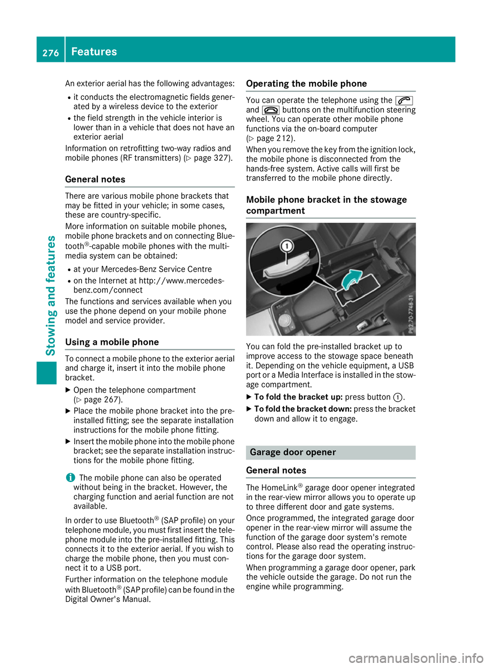
compartment You can fold the pre-installed bracket up to
improve access to the stowage space beneath
it. Depending on the vehicle equipment, a USB
port or a Media Interface is installed in the stow- age compartment.
X To fold the bracket up: press button:.
X To fold the bracket down: press the bracket
down and allow it to engage. Garage door opener
General notes The HomeLink
®
garage door opener integrated
in the rear-view mirror allows you to operate up
to three different door and gate systems.
Once programmed, the integrated garage door
opener in the rear-view mirror will assume the
function of the garage door system's remote
control. Please also read the operating instruc-
tions for the garage door system.
When programming a garage door opener, park
the vehicle outside the garage. Do not run the
engine while programming. 276
FeaturesSto
wing an d features
Page 280 of 345

The garage door opener is only available for cer-
tain countries. Observe the legal requirements
for each individual country.
The HomeLink ®
garage door opener is compat-
ible with most European garage and gate opener
drives. More information on HomeLink ®
and/or
compatible products is available:
R at a qualified specialist workshop
R via the HomeLink ®
Hotline
(0) 08000 466 354 65 or alternatively
+49 (0) 6838 907-277
R on the Internet at http://www.homelink.com
Important safety notes G
WARNING
When you operate or program the garage door with the integrated garage door opener, per-
sons in the range of movement of the garage
door can become trapped or struck by the
garage door. There is a risk of injury.
When using the integrated garage door
opener, always make sure that nobody is
within the range of movement of the garage
door. G
WARNING
Combustion engines emit poisonous exhaust
gases such as carbon monoxide. Inhaling
these exhaust gases leads to poisoning. There is a risk of fatal injury. Therefore never leave
the engine running in enclosed spaces with-
out sufficient ventilation.
Programming Programming buttons
Pay attention to the "Important safety notes"
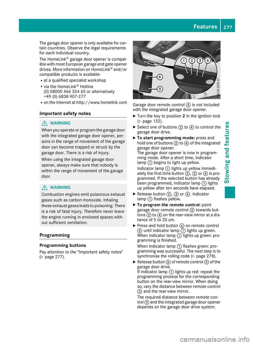
(Y page 277). Garage door remote control
Ais not included
with the integrated garage door opener.
X Turn the key to position 2in the ignition lock
(Y page 132).
X Select one of buttons ;to? to control the
garage door drive.
X To start programming mode: press and
hold one of buttons ;to? of the integrated
garage door opener.
The garage door opener is now in program-
ming mode. After a short time, indicator
lamp :begins to light up yellow.
Indicator lamp :lights up yellow immedi-
ately the first time button ;,=or? is pro-
grammed. If the selected button has already
been programmed, indicator lamp :lights
up yellow after ten seconds have elapsed.
X Release button ;,=or?. Indicator
lamp :flashes yellow.
X To program the remote control: point
garage door remote control Atowards but-
tons ;to? on the rear-view mirror at a dis-
tance of 5 to 20 cm.
X Press and hold button Bon remote control
A until indicator lamp :lights up green.
When indicator lamp :lights up green: pro-
gramming is finished.
When indicator lamp :flashes green: pro-
gramming was successful. The next step is to
synchronise the rolling code (Y page 278).
X Release button Bof remote control Aof the
garage door drive.
If indicator lamp :lights up red: repeat the
programming process for the corresponding
button on the rear-view mirror. When doing
so, vary the distance between remote control A and the rear-view mirror.
The required distance between remote con-
trol Aand the integrated garage door opener
depends on the garage door drive system. Features
277Stowing and features Z
Page 281 of 345

Several attempts may be required. You
should test every position for at least
25 seconds before trying another position.
Synchronising the rolling code
Observe the "Important safety notes"
(Y page 277).
If the garage door system uses a rolling code,
you will also have to synchronise the garage
door system with the integrated garage door
opener in the rear-view mirror. To do this, you
will need to use the programming button on the
door drive control panel. The programming but-
ton may be placed at different locations depend- ing on the manufacturer. It is usually located on
the door drive unit on the garage ceiling.
Familiarise yourself with the garage door drive
operating instructions, e.g. under "Program-
ming of additional remote controls", before car-
rying out the following steps.
Your vehicle must be within range of the garage
door or gate opener drive. Make sure that nei-
ther your vehicle nor any persons/objects are
present within the sweep of the door or gate.
X Turn the key to position 2in the ignition lock
(Y page 132).
X Get out of the vehicle.
X Press the programming button on the door
drive unit.
Usually, you now have 30 seconds to initiate
the next step.
X Get into the vehicle.
X Press previously programmed button ;,=
or ? of the integrated garage door opener
until the door closes.
The rolling code synchronisation is then com- plete.
Problems when programming
If you have problems when programming the
integrated garage door opener, please note the following:
R Check the transmitter frequency used by
garage door drive remote control Aand
whether it is supported. The transmitter fre-
quency can usually be found on the back of
the garage door drive remote control.
R Replace the batteries in garage door remote
control A. This increases the likelihood that
garage door remote control Awill transmit a
strong and precise signal to the integrated
garage door opener in the rear-view mirror. R
When programming, hold remote control A
at varying distances and angles from the but-
ton which you are programming. Try various
angles at a distance between 5and 20cm or
at the same angle but at varying distances.
R If there is another remote control for the same
garage door drive, perform the programming
steps again using this remote control. Before
performing these steps, make sure that new
batteries have been fitted in garage door drive remote control A.
R Note that some remote controls transmit only
for a limited period (the indicator lamp on theremote control goes out). Press button Bon
remote control Aagain before transmission
ends.
R Align the aerial cable of the garage door
opener unit. This can improve signal recep-
tion/transmission.
Opening or closing the garage door Once programmed, the integrated garage door
opener will assume the function of the garage
door system's remote control. Please also read
the operating instructions for the garage door
system.
X Turn the key to position 2in the ignition lock
(Y page 132).
X Press button ;,=or? which you have
programmed to operate the garage door.
Garage door system with a fixed code: indi-
cator lamp :lights up green.
Garage door system with a rolling code: indi-
cator lamp :flashes green.
The transmitter will transmit a signal for as
long as the button is pressed. The transmis-
sion is halted after a maximum of ten seconds
and indicator lamp :lights up yellow.
X Press button ;,=or? again if necessary.
Clearing the memory Make sure that you clear the memory of the
integrated garage door opener before selling the
vehicle. 278
FeaturesStowing and features
Page 282 of 345

X
Turn the key to position 2in the ignition lock
(Y page 132).
X Press and hold buttons ;and ?.
The indicator lamp initially lights up yellow
and then green.
X Release buttons ;and ?.
The memory of the integrated garage door
opener in the rear-view mirror is cleared.
Frequencies Europe
Country Radio type approval num-
ber
Frequency range (MHz)
AD (Andorra) 20 July 2005
MHz: 27, 30, 40, 433, 868
AT (Austria) Article 6 of Directive
1999/5/EC R&TTE 18 May
05
MHz: 27, 40, 433, 868
BE (Belgium) Article 6 of Directive
1999/5/EC R&TTE 18 May
05
MHz: 27, 40, 433, 868
BG (Bulgaria) Article 6 of Directive
1999/5/EC R&TTE 12 April
07
MHz: 27, 40, 433, 868
CH (Switzer-
land) Article 6 of Directive
1999/5/EC R&TTE 14357 27
May 05
MHz: 27, 40, 433, 868 CY (Cyprus) Article 6 of Directive
1999/5/EC R&TTE 5 May 05
MHz: 27, 40, 433, 868 CZ (Czech
Republic) General Licence GL-30/R/
2000 Reg No. 844 13 May 05
MHz: 27, 40, 433 DK (Den-
mark) Article 6 of Directive
1999/5/EC R&TTE 20 April
05
MHz: 27, 40, 433, 868 Country Radio type approval num-
ber
Frequency range (MHz)
DE (Ger-
many) Article 6 of Directive
1999/5/EC R&TTE 7519301
29 April 05
MHz: 27, 40, 433, 868
EE (Estonia) Article 6 of Directive
1999/5/EC R&TTE 11 May
05
MHz: 27, 40, 433, 868
ES (Spain) 000438/2005,
000439/2005,
000440/2005
000441/2005,
000445/2005,
000446/2005
000447/2005
MHz: 27, 40, 433, 868
FI (Finland) Article 6 of Directive
1999/5/EC R&TTE 10668 13
May 05
MHz: 27, 40, 433, 868 FR (France) Article 6 of Directive
1999/5/EC R&TTE 10668 13
May 05
MHz: 27, 30, 40, 433, 868 GI (Gibraltar) Article 6 of Directive
1999/5/EC R&TTE 10668 13
May 05 (UK)
MHz: 27, 40, 418, 433, 868 GR (Greece) Article 6 of Directive
1999/5/EC R&TTE
11409/18/4/2005 18 May
05
MHz: 27, 40, 433, 868
HR (Croatia) SDR 224/06
MHz: 27, 40, 433, 868
HU (Hungary) Article 6 of Directive
1999/5/EC R&TTE 18 May
05
MHz: 27, 40, 433, 868 Features
279Stowing and features Z