2015 MERCEDES-BENZ CLA SHOOTING BRAKE lock
[x] Cancel search: lockPage 245 of 421
X
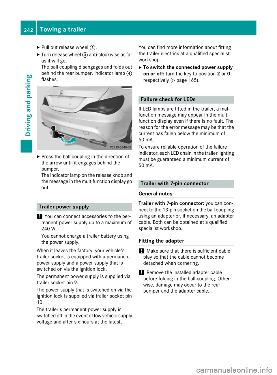
Pull out release wheel =.
X Turn release wheel =anti-clockwise as far
as it will go.
The ball coupling disengages and folds out
behind the rear bumper. Indicator lamp ?
flashes. X
Press the ball coupling in the direction of
the arrow until it engages behind the
bumper.
The indicator lamp on the release knob and
the message in the multifunction display go
out. Trailer power supply
! You can connect accessories to the per-
manent power supply up to a maximum of
240 W.
You cannot charge a trailer battery using
the power supply.
When it leaves the factory, your vehicle's
trailer socket is equipped with a permanent
power supply and a power supply that is
switched on via the ignition lock.
The permanent power supply is supplied via
trailer socket pin 9.
The power supply that is switched on via the
ignition lock is supplied via trailer socket pin
10.
The trailer's permanent power supply is
switched off in the event of low vehicle supply
voltage and after six hours at the latest. You can find more information about fitting
the trailer electrics at a qualified specialist
workshop.
X To switch the connected power supply
on or off: turn the key to position 2or 0
respectively (Y page 165). Failure check for LEDs
If LED lamps are fitted in the trailer, a mal-
function message may appear in the multi-
function display even if there is no fault. The
reason for the error message may be that the
current has fallen below the minimum of
50 mA.
To ensure reliable operation of the failure
indicator, each LED chain in the trailer lighting
must be guaranteed a minimum current of
50 mA. Trailer with 7-pin connector
General notes Trailer with 7-pin connector:
you can con-
nect to the 13-pin socket on the ball coupling
using an adapter or, if necessary, an adapter
cable. Both can be obtained at a qualified
specialist workshop.
Fitting the adapter !
Make sure that there is sufficient cable
play so that the cable cannot become
detached when cornering.
! Remove the installed adapter cable
before folding in the ball coupling. Other-
wise, damage may occur to the rear
bumper and the adapter cable. 242
Towing a trailerDriving and parking
Page 246 of 421
X
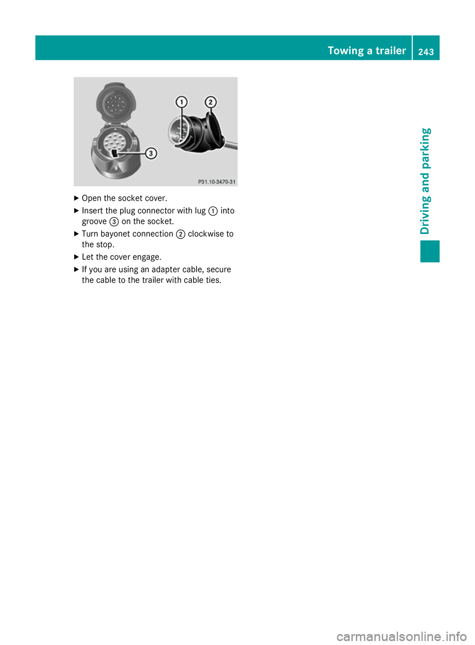
Open the socket cover.
X Insert the plug connector with lug :into
groove =on the socket.
X Turn bayonet connection ;clockwise to
the stop.
X Let the cover engage.
X If you are using an adapter cable, secure
the cable to the trailer with cable ties. Towing a trailer
243Driving and parking Z
Page 249 of 421
Useful information
i This Owner's Manual describes all mod-
els, series and optional equipment for your
vehicle that were available at the time of
going to press. National variations are pos- sible. Note that your vehicle may not be
equipped with all of the functions descri-
bed. This is also the case for systems and
functions relevant to safety.
i Read the information on qualified special-
ist workshops: (Y page 25). Important safety notes
G
WARNING
Operating the integrated information systems and communications equipment in the vehicle
while driving will distract you from traffic con-
ditions. You could then lose control of the
vehicle. There is a risk of an accident.
Only operate these devices if road traffic con-
ditions permit. If you are unsure about the
surrounding conditions, pull over to a safe
location and make entries only while the vehi-
cle is stationary.
You must observe the legal requirements for
the country in which you are currently driving when operating the on-board computer. G
WARNING
If the instrument cluster has failed or mal-
functioned, you may not recognise function
restrictions relevant to safety. The operating
safety of your vehicle may be impaired. There is a risk of an accident.
Drive on carefully. Have the vehicle checked
at a qualified specialist workshop immedi-
ately.
The on-board computer only shows messages
or warnings from certain systems in the mul- tifunction display. You should therefore make
sure your vehicle is operating safely at all
times. If the operating safety of your vehicle is
impaired, park the vehicle safely as soon as
possible. Contact a qualified specialist work-
shop.
For an overview, see the instrument panel
illustration (Y
page 32). Displays and operation
Instrument cluster lighting
The light sensor in the instrument cluster
automatically controls the brightness of the
multifunction display. In daylight, the displays
in the instrument cluster are not illuminated.
The lighting in the instrument cluster, in the
displays and the controls in the vehicle inte-
rior can be adjusted using the brightness con-
trol knob.
The brightness control knob is located on the bottom left of the instrument cluster
(Y page 32).
X Turn the brightness control knob clockwise
or anti-clockwise.
If the light switch is set to the Ã,Tor
L position, the brightness is dependent
upon the brightness of the ambient light. Speedometer with segments
The speedometer is divided into segments
only on vehicles with DISTRONIC PLUS.
The segments in the speedometer indicate
which speed range is available.
R Variable SPEEDTRONIC activated
(Y page 202):
The segments light up from the start of the
scale to the selected limit speed.
R DISTRONIC PLUS activated (Y page 204):
One or two segments in the set speed
range light up.
R DISTRONIC PLUS detects a vehicle in front
moving more slowly than the stored speed: 246
Displays and operationOn-board computer and displays
Page 250 of 421

The segments between the speed of the
vehicle in front and the stored speed light
up. Rev counter
! Do not drive in the overrevving range.
Doing so will damage the engine.
The red band in the rev counter indicates the
engine's overrevving range.
The engine is limited within a range to protect the engine when the red band is reached. Outside temperature display
You should pay special attention to road con-
ditions when temperatures are around freez-
ing point.
Bear in mind that the outside temperature
display indicates the measured air tempera-
ture and not the road surface temperature.
The outside temperature display is in the mul- tifunction display (Y page 249).
There is a short delay before a change in out- side temperature appears in the multifunc-
tion display. Coolant temperature gauge
G
WARNING
If you open the bonnet while the engine is
overheating or while there is a fire in the
engine compartment, you could come into
contact with hot gases or other leaking ser-
vice products. There is a danger of injury.
Allow an overheating engine to cool down
before opening the bonnet. If there is a fire in the engine compartment, leave the bonnet
closed and notify the fire brigade.
The coolant temperature gauge is in the
instrument cluster on the right-hand side
(Y page 32). Under normal operating conditions and with
the specified coolant level, the coolant tem-
perature may rise to 120 †.
At high outside temperatures and when driv-
ing uphill, the coolant temperature may rise
to the end of the scale. Operating the on-board computer
Overview :
Multifunction display
; Right control panel
= Left control panel
X To activate the on-board computer: turn
the key to position 1in the ignition lock.
You can control the multifunction display and
the settings in the on-board computer using
the buttons on the multifunction steering
wheel. Displays and operation
247On-board computer and displays Z
Page 263 of 421
ting switches permanent SPEEDTRONIC
off.
X Press the abutton to store the entry.
For further information on permanent SPEED-
TRONIC (Y page 204).
Activating/deactivating the automatic
locking feature
X Press the =or; button on the steer-
ing wheel to select the Settings
Settingsmenu.
X Press the :or9 button to select the
Vehicle
Vehicle submenu.
X Press ato confirm.
X Press the :or9 button to select the
Automatic door locks
Automatic door locks function.
If the Automatic door locks
Automatic door locks function is
switched on, the multifunction display
shows the doors in orange.
X Press the abutton to save the setting.
If you activate the Automatic door locks
Automatic door locks
function, the vehicle is centrally locked above
a speed of around 15 km/h.
For further information on the automatic lock- ing feature; see (Y page 95).
Activating/deactivating the acoustic
locking confirmation
If you switch on the Acoustic
Acoustic Lock Lockfunction,
an acoustic signal sounds when you lock the
vehicle.
X Press the =or; button on the steer-
ing wheel to select the Settings
Settings menu.
X Press the :or9 button to select the
Vehicle Vehicle submenu.
X Press ato confirm.
X Press the :or9 button to select the
Acoustic Lock
Acoustic Lock function.
If the Acoustic
Acoustic Lock
Lockfunction is activated,
the & symbol in the multifunction dis-
play lights up orange.
X Press the abutton to save the setting. Heating Auxiliary heating departure time
G
DANGER
If the exhaust pipe is blocked or sufficient
ventilation is not possible, toxic exhaust
fumes can enter the vehicle, especially car-
bon monoxide. This is the case, e.g. in
enclosed spaces, or if the vehicle is stuck in
snow. There is a risk of fatal injuries.
You should switch off the auxiliary heating in
enclosed spaces which do not have an extrac- tion system, e.g. a garage. If the vehicle is
stuck in snow and you must leave the auxiliary
heating running, keep the exhaust pipe and
the area around the vehicle clear of snow. To guarantee a sufficient supply of fresh air, open
a window on the side of the vehicle away from the wind. G
WARNING
When the auxiliary heating is switched on,
parts of the vehicle can become very hot.
Flammable materials such as leaves, grass or twigs may ignite if they come into contact
with:
R hot parts of the exhaust system
R the exhaust gas itself
There is a risk of fire.
When the auxiliary heating is switched on,
make sure that:
R no flammable materials come into contact
with hot vehicle components
R the exhaust gas can escape from the
exhaust pipe unhindered
R the exhaust gas does not come into contact
with flammable materials.
! Operating the auxiliary heating/ventila-
tion draws on the vehicle battery. After you
have heated or ventilated the vehicle a
maximum of two times, drive for a longer
distance.
Only vehicles with auxiliary heating have this
function. 260
Menus and submenusOn-board computer and displays
Page 264 of 421
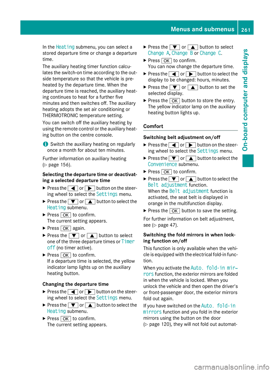
In the
Heating
Heating submenu, you can select a
stored departure time or change a departure
time.
The auxiliary heating timer function calcu-
lates the switch-on time according to the out-
side temperature so that the vehicle is pre-
heated by the departure time. When the
departure time is reached, the auxiliary heat- ing continues to heat for a further five
minutes and then switches off. The auxiliary
heating adopts the set air conditioning or
THERMOTRONIC temperature setting.
You can switch off the auxiliary heating by
using the remote control or the auxiliary heat- ing button on the centre console.
i Switch the auxiliary heating on regularly
once a month for about ten minutes.
Further information on auxiliary heating
(Y page 156).
Selecting the departure time or deactivat-
ing a selected departure time
X Press the =or; button on the steer-
ing wheel to select the Settings
Settings menu.
X Press the :or9 button to select the
Heating
Heating submenu.
X Press ato confirm.
The current setting appears.
X Press aagain.
X Press the :or9 button to select
one of the three departure times or Timer Timer
off
off (no timer active).
X Press ato confirm.
If a departure time is selected, the yellow
indicator lamp lights up on the auxiliary
heating button.
Changing the departure time
X Press the =or; button on the steer-
ing wheel to select the Settings Settingsmenu.
X Press the :or9 button to select the
Heating
Heating submenu.
X Press ato confirm.
The current setting appears. X
Press the :or9 button to select
Change A Change A, Change B Change BorChange C
Change C.
X Press ato confirm.
You can now change the departure time.
X Press the =or; button to select the
display to be changed: hours, minutes.
X Press the :or9 button to set the
selected display.
X Press the abutton to store the entry.
The yellow indicator lamp on the auxiliary
heating button lights up.
Comfort Switching belt adjustment on/off
X Press the =or; button on the steer-
ing wheel to select the Settings
Settings menu.
X Press the :or9 button to select the
Convenience
Convenience submenu.
X Press ato confirm.
X Press the :or9 button to select the
Belt adjustment Belt adjustment function.
When the Belt adjustment Belt adjustment function is
activated, the seat belt is displayed in
orange in the multifunction display.
X Press the abutton to save the setting.
For further information on belt adjustment,
see (Y page 47).
Switching the fold mirrors in when lock-
ing function on/off
This function is only available when the vehi-
cle is equipped with the electrical fold-in func-
tion.
When you activate the Auto.
Auto. fold-in fold-in mir‐
mir‐
rors
rors function, the exterior mirrors are folded
in when the vehicle is locked. When you
unlock the vehicle and then open the driver's or front-passenger door, the exterior mirrors
fold out again.
If you have switched on the Auto. Auto.fold-in
fold-in
mirrors
mirrors function and you fold in the exterior
mirrors using the button on the door
(Y page 120), they will not fold out automat- Menus and submenus
261On-board computer and displays Z
Page 266 of 421
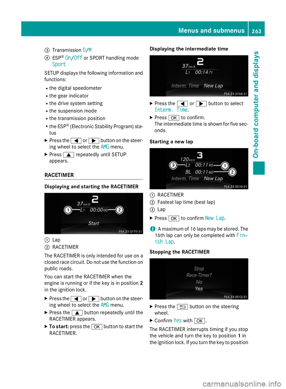
=
Transmission D
D/MM
? ESP ®
On
On/Off Off or SPORT handling mode
Sport
Sport
SETUP displays the following information and
functions:
R the digital speedometer
R the gear indicator
R the drive system setting
R the suspension mode
R the transmission position
R the ESP ®
(Electronic Stability Program) sta-
tus
X Press the =or; button on the steer-
ing wheel to select the AMG
AMGmenu.
X Press 9repeatedly until SETUP
appears.
RACETIMER Displaying and starting the RACETIMER
:
Lap
; RACETIMER
The RACETIMER is only intended for use on a closed race circuit. Do not use the function on
public roads.
You can start the RACETIMER when the
engine is running or if the key is in position 2
in the ignition lock.
X Press the =or; button on the steer-
ing wheel to select the AMG
AMG menu.
X Press the 9button repeatedly until the
RACETIMER appears.
X To start: press the abutton to start the
RACETIMER. Displaying the intermediate time
X
Press the =or; button to select
Interm. Time Interm. Time.
X Press ato confirm.
The intermediate time is shown for five sec-
onds.
Starting a new lap :
RACETIMER
; Fastest lap time (best lap)
= Lap
X Press ato confirm New Lap
New Lap.
i A maximum of 16 laps may be stored. The
16th lap can only be completed with Fin‐
Fin‐
ish Lap
ish Lap.
Stopping the RACETIMER X
Press the %button on the steering
wheel.
X Confirm Yes
Yeswith a.
The RACETIMER interrupts timing if you stop
the vehicle and turn the key to position 1in
the ignition lock. If you turn the key to position Menus and submenus
263On-board computer and displays Z
Page 269 of 421

Safety systems
Display messages
Possible causes/consequences and
M
MSolutions !÷
currently unavail‐ currently unavail‐
able See Owner's able See Owner's
Manual Manual ABS (Anti-lock Braking System), BAS (Brake Assist System), ESP
®
(Electronic Stability Program), ESP ®
trailer stabilisation, the HOLD
function, hill start assist and PRE-SAFE ®
are temporarily unavail-
able.
The adaptive brake lights and COLLISION PREVENTION ASSIST
PLUS may also have failed.
In addition, the !,÷andå warning lamps may light up
in the instrument cluster.
ATTENTION ASSIST is deactivated.
Possible causes:
R Self-diagnosis is not yet complete
R The on-board voltage may be insufficient.
G WARNING
The brake system continues to function normally, but without the functions listed above. The wheels could therefore lock if you
brake hard, for example.
The steerability and braking characteristics may be severely affec-ted. The braking distance may increase in an emergency braking
situation.
If ESP ®
is not operational, ESP ®
is unable to stabilise the vehicle.
There is an increased danger of skidding and risk of an accident.
X Carefully drive on a suitable stretch of road, making slight steer-
ing movements, at a speed above 20 km/h.
If the display message disappears, the functions mentioned
above are available again.
If the multifunction display still shows the display message:
X Drive on carefully.
X Consult a qualified specialist workshop immediately. !÷
inoperative See inoperative See
Owner's Manual Owner's Manual ABS, BAS, ESP
®
, ESP ®
trailer stabilisation, the HOLD function, hill
start assist and PRE-SAFE ®
are not available due to a malfunction.
The adaptive brake lights and COLLISION PREVENTION ASSIST
PLUS may also have failed.
The !, ÷, åandJ warning lamps may also light up
in the instrument cluster.
ATTENTION ASSIST is deactivated.
G WARNING 266
Display messagesOn-board computer and displays