2015 MERCEDES-BENZ B-CLASS SPORTS tailgate
[x] Cancel search: tailgatePage 261 of 346
floor away so that it engages in the guide onthe upper level.
Cargo compartment floor ;engages in
the upper position.
iCarry out this step using both hands.
X To lower: raise cargo compartment
floor ;slightly using handle :and pull it
towards you.
X Lower cargo compartment floor ;again
slowly. Whilst doing so, press the cargo
compartment floor into the lower level.
Cargo compartment floor ;engages in
the lower position.
Roof carrier
Important safety notes
GWARNING
When you load the roof, the center of gravity
of the vehicle rises and the driving character- istics change. If you exceed the maximum roof
load, the driving characteristics, as well as
steering and braking, will be greatly impaired.There is a risk of an accident.
Never exceed the maximum roof load and
adjust your driving style.
!Mercedes-Benz recommends that you
only use roof carriers that have been tested
and approved for Mercedes-Benz vehicles.
This helps to prevent damage to the vehi-cle.
Position the load on the roof rack in such a
way that the vehicle will not sustain dam-
age even when it is in motion.
Ensure that, depending on the vehicle's
equipment, you can raise the panorama
roof with power tilt/sliding panel fully and
open the tailgate fully when the roof carrier is installed.
You will find information on the maximum roof
load in the "Technical data" section( Y page 341). An incorrectly secured roof carrier or roof
load may become detached from the vehicle.
You must therefore ensure that you observe
the roof carrier manufacturer's installation
instructions.
Attaching the roof carrier
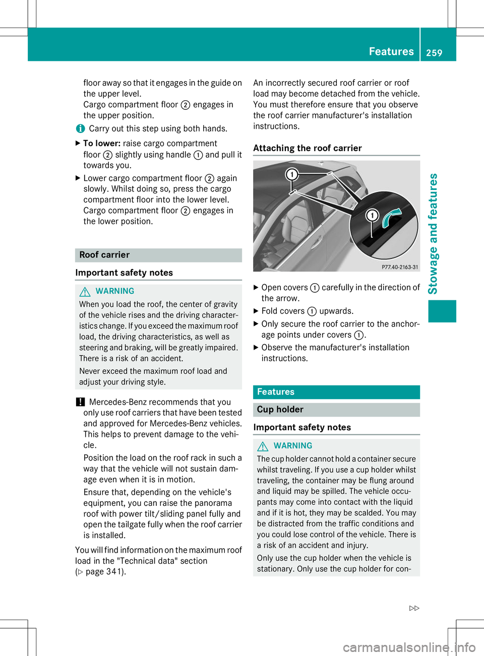
X Open covers :carefully in the direction of
the arrow.
X Fold covers :upwards.
X Only secure the roof carrier to the anchor-
age points under covers :.
X Observe the manufacturer's installation
instructions.
Features
Cup holder
Important safety notes
GWARNING
The cup holder cannot hold a container secure whilst traveling. If you use a cup holder whilsttraveling, the container may be flung around
and liquid may be spilled. The vehicle occu-
pants may come into contact with the liquid
and if it is hot, they may be scalded. You may
be distracted from the traffic conditions and
you could lose control of the vehicle. There is a risk of an accident and injury.
Only use the cup holder when the vehicle is
stationary. Only use the cup holder for con-
Features259
Stowage and features
Z
Page 269 of 346
Compass
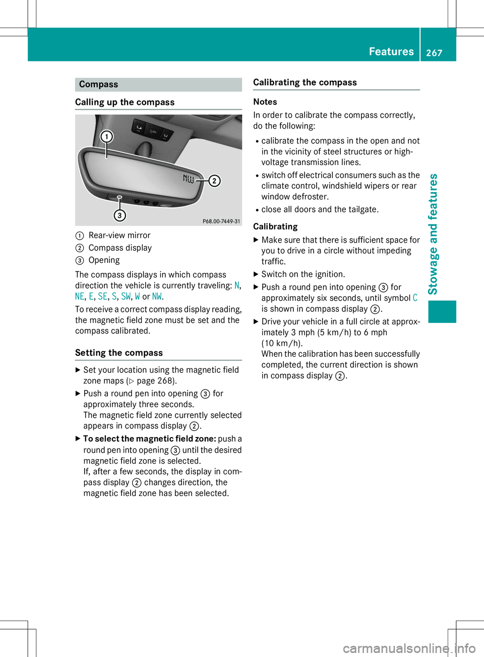
Calling up the compass
:Rear-view mirror
;Compass display
=Opening
The compass displays in which compass
direction the vehicle is currently traveling:
N,
NE,E,SE,S,SW,WorNW.
To receive a correct compass display reading, the magnetic field zone must be set and the
compass calibrated.
Setting the compass
X Set your location using the magnetic field
zone maps ( Ypage 268).
X Push a round pen into opening =for
approximately three seconds.
The magnetic field zone currently selected
appears in compass display ;.
X To select the magnetic field zone: push a
round pen into opening =until the desired
magnetic field zone is selected.
If, after a few seconds, the display in com-
pass display ;changes direction, the
magnetic field zone has been selected.
Calibrating the compass
Notes
In order to calibrate the compass correctly,
do the following:
R calibrate the compass in the open and not
in the vicinity of steel structures or high-
voltage transmission lines.
R switch off electrical consumers such as the
climate control, windshield wipers or rear
window defroster.
R close all doors and the tailgate.
Calibrating
X Make sure that there is sufficient space for
you to drive in a circle without impeding
traffic.
X Switch on the ignition.
X Push a round pen into opening =for
approximately six seconds, until symbol
C
is shown in compass display ;.
X Drive your vehicle in a full circle at approx-
imately 3 mph (5 km/h)to 6 mph
(10 km/h).
When the calibration has been successfully
completed, the current direction is shown
in compass display ;.
Features267
Sto wage an d features
Z
Page 286 of 346
Useful information
iThis Operator's Manual describes all
models and all standard and optional equip- ment of your vehicle available at the time of
publication of the Operator's Manual.
Country-specific differences are possible.
Please note that your vehicle may not be
equipped with all features described. This
also applies to safety-related systems and
functions.
iRead the information on qualified special-
ist workshops ( Ypage 24).
Where will I find...?
Vehicle tool kit
General notes
Vehicles with a TIREFIT kit: the TIREFIT kit is
located in the stowage well under the cargo
compartment floor.
Vehicles with a tire-change tool kit: the tire-
change tool kit is in the stowage well under
the cargo compartment floor.
For vehicles with an emergency spare wheel, see "Removing the emergency spare wheel" ( Y page 330).
iApart from certain country-specific varia-
tions, the vehicles are not equipped with a
tire-change tool kit. Some tools for chang-
ing a wheel are specific to the vehicle. For
more information on which tire changing
tools are required and approved to perform
a wheel change on your vehicle, consult a
qualified specialist workshop.
Tools required for changing a wheel may
include, for example:
R Jack
R Wheel chock
R Lug wrench
R Alignment bolt
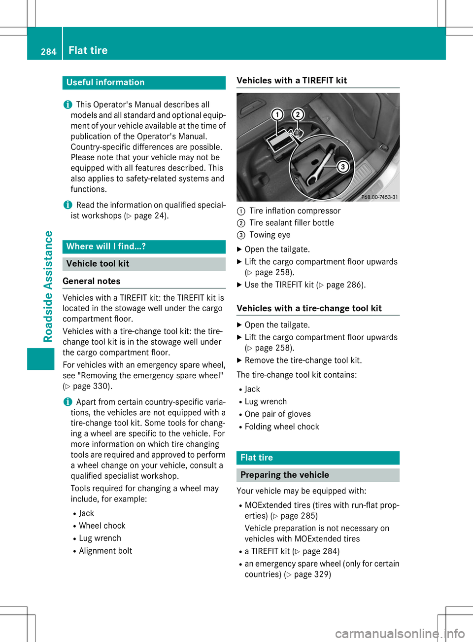
Vehicles with a TIREFIT kit
:Tire inflation compressor
;Tire sealant filler bottle
=Towing eye
X Open the tailgate.
X Lift the cargo compartment floor upwards (Y page 258).
X Use the TIREFIT kit ( Ypage 286).
Vehicles with a tire-change tool kit
X
Open the tailgate.
X Lift the cargo compartment floor upwards (Y page 258).
X Remove the tire-change tool kit.
The tire-change tool kit contains: R Jack
R Lug wrench
R One pair of gloves
R Folding wheel chock
Flat tire
Preparing the vehicle
Your vehicle may be equipped with:
R MOExtended tires (tires with run-flat prop-
erties) ( Ypage 285)
Vehicle preparation is not necessary on
vehicles with MOExtended tires
R a TIREFIT kit ( Ypage 284)
R an emergency spare wheel (only for certain
countries) ( Ypage 329)
284Flat tire
Roadside Assistance
Page 326 of 346
Observe the following when raising the vehicle:
R To raise the vehicle, only use the vehicle-
specific jack that has been tested and
approved by Mercedes-Benz. If used incor-
rectly, the jack could tip over with the vehi- cle raised.
R The jack is designed only to raise and hold
the vehicle for a short time while a wheel
is being changed. It is not suited for per-
forming maintenance work under the vehi-
cle.
R Avoid changing the wheel on uphill and
downhill slopes.
R Before raising the vehicle, secure it from
rolling away by applying the parking brake
and inserting wheel chocks. Do not disen-
gage the parking brake while the vehicle is
raised.
R The jack must be placed on a firm, flat and
non-slip surface. On a loose surface, a
large, flat, load-bearing underlay must be
used. On a slippery surface, a non-slip
underlay must be used, e.g. rubber mats.
R Do not use wooden blocks or similar
objects as a jack underlay. Otherwise, the
jack will not be able to achieve its load-
bearing capacity due to the restrictedheight.
R Make sure that the distance between the
underside of the tires and the ground does
not exceed 1.2 in (3 cm).
R Never place your hands and feet under the
raised vehicle.
R Do not lie under the vehicle.
R Do not start the engine when the vehicle is
raised.
R Never open or close a door or the tailgate
when the vehicle is raised.
R Make sure that no persons are present in
the vehicle when the vehicle is raised.
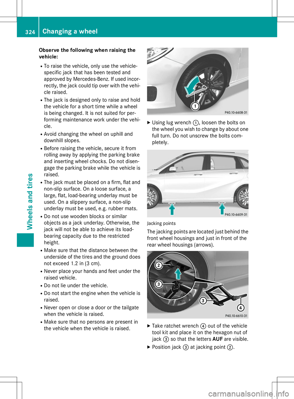
XUsing lug wrench :, loosen the bolts on
the wheel you wish to change by about one full turn. Do not unscrew the bolts com- pletely.
Jacking points
The jacking points are located just behind the front wheel housings and just in front of the
rear wheel housings (arrows).
X Take ratchet wrench ?out of the vehicle
tool kit and place it on the hexagon nut of jack =so that the letters AUFare visible.
X Position jack =at jacking point ;.
324Changing a wheel
Wheels and tires
Page 332 of 346
You should regularly check the pressure of
the emergency spare wheel, particularly prior
to long trips, and correct the pressure as nec- essary ( Ypage 305). The value on the wheel is
valid. In addition, the emergency spare wheel
tire pressure can be found under "Technical
data" ( Ypage 331).
An emergency spare wheel may also be
mounted against the direction of rotation.
Observe the time restriction on use as well as
the speed limitation specified on the emer-
gency spare wheel.
Replace the tires after six years at the latest, regardless of wear. This also applies to the
emergency spare wheel.
When you are driving with the emergency
spare wheel mounted, the tire pressure loss
warning system cannot function reliably. Only
restart the tire pressure loss warning system when the defective wheel has been replaced
with a new wheel.
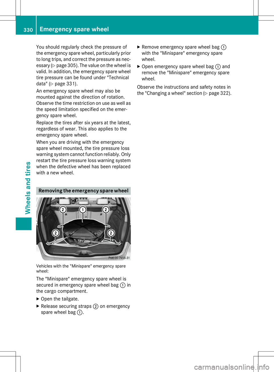
Removing the emergency spare wheel
Vehicles with the "Minispare" emergency spare wheel:
The "Minispare" emergency spare wheel is
secured in emergency spare wheel bag :in
the cargo compartment.
X Open the tailgate.
X Release securing straps ;on emergency
spare wheel bag :. X
Remove emergency spare wheel bag :
with the "Minispare" emergency sparewheel.
X Open emergency spare wheel bag :and
remove the "Minispare" emergency sparewheel.
Observe the instructions and safety notes in
the "Changing a wheel" section ( Ypage 322).
330Emergency spare wheel
Wheels and tires