2015 MERCEDES-BENZ B-Class ELECTRIC check oil
[x] Cancel search: check oilPage 133 of 338

R
in transmission position N
R during and after ESP stability control
If you do not make an additional effort to
apply the brake yourself, the braking effect
may not be sufficient. If necessary, counter-
act the reduced regenerative braking effect
by applying the brake yourself.
Before commencing your journey, ensure that the charging cable required for charging the
high-voltage battery is in the vehicle. Key positions
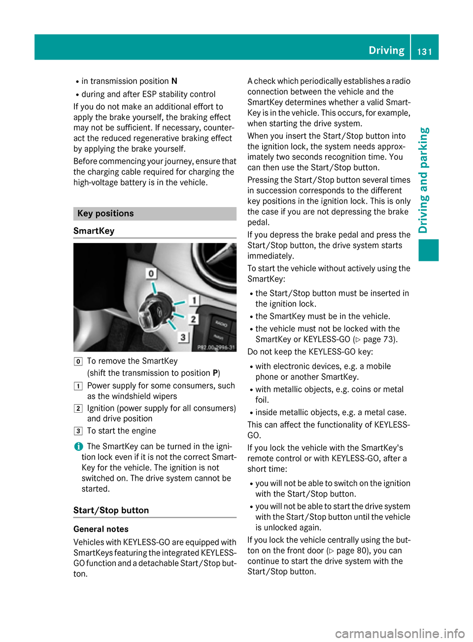
SmartKey g
To remove the SmartKey
(shift the transmission to position P)
1 Power supply for some consumers, such
as the windshield wipers
2 Ignition (power supply for all consumers)
and drive position
3 To start the engine
i The SmartKey can be turned in the igni-
tion lock even if it is not the correct Smart- Key for the vehicle. The ignition is not
switched on. The drive system cannot be
started.
Start/Stop button General notes
Vehicles with KEYLESS-GO are equipped with
SmartKeys featuring the integrated KEYLESS- GO function and a detachable Start/Stop but-
ton. A check which periodically establishes a radio
connection between the vehicle and the
SmartKey determines whether a valid Smart- Key is in the vehicle. This occurs, for example,
when starting the drive system.
When you insert the Start/Stop button into
the ignition lock, the system needs approx-
imately two seconds recognition time. You
can then use the Start/Stop button.
Pressing the Start/Stop button several times
in succession corresponds to the different
key positions in the ignition lock. This is only
the case if you are not depressing the brake
pedal.
If you depress the brake pedal and press the
Start/Stop button, the drive system starts
immediately.
To start the vehicle without actively using the SmartKey:
R the Start/Stop button must be inserted in
the ignition lock.
R the SmartKey must be in the vehicle.
R the vehicle must not be locked with the
SmartKey or KEYLESS-GO (Y page 73).
Do not keep the KEYLESS-GO key:
R with electronic devices, e.g. a mobile
phone or another SmartKey.
R with metallic objects, e.g. coins or metal
foil.
R inside metallic objects, e.g. a metal case.
This can affect the functionality of KEYLESS-
GO.
If you lock the vehicle with the SmartKey's
remote control or with KEYLESS-GO, after a
short time:
R you will not be able to switch on the ignition
with the Start/Stop button.
R you will not be able to start the drive system
with the Start/Stop button until the vehicle is unlocked again.
If you lock the vehicle centrally using the but-
ton on the front door (Y page 80), you can
continue to start the drive system with the
Start/Stop button. Driving
131Driving and parking Z
Page 147 of 338

X
To switch on: press button:.
The green Indicator lamp lights up.
X To switch off: press button:.
The indicator lamp goes out.
RANGE PLUS switches off automatically if: R the charging cable is disconnected or
R the charging process is complete
Information on charging with RANGE PLUS
(Y page 196).
Notes on battery care Avoid storing or transporting the vehicle in
high temperatures over a long period (e.g.
container transport).
If you park the vehicle and leave it stationary
for longer periods, connect it to a power sup-
ply.
Temperatures below Ò13‡(Ò25 †) and over
104 ‡ (40 †), which affect the vehicle for a
period of more than seven days, can cause
irreversible damage.
Conditions of use Observe the following notes:
R information on exceptions and limitations
in warranty documentation and in the rela-
ted Maintenance Booklet
R maintenance notes for the high-voltage
battery in the Maintenance Booklet Handling the charging cable and charg-
ing cable controls Do not leave the charging cable controls
(Y page 146) hanging loose from an electrical
outlet. Otherwise, this could result in a poor
contact with the electrical outlet and mal-
functions when charging the vehicle.
To ensure that the brackets within the charg- ing cable controls are not subjected to incor-
rect loads, observe the following:
R Never lift or carry the controls by the charg-
ing cable connector or the mains plug.
R To transport the charging cable, the coiled
part can be:
- wrapped around the controls or
- secured to the housing of the controls
Heat generated by the charging cable
and charging cable connector Pay attention to the "Important safety notes"
(Y page 140).
During the charging process, the charging
cable and charging cable connector may heat
up.
The charging cable and charging cable con-
nector will only heat up within the permissible
limiting values, provided that:
R the power supply and the charging cable
are not damaged
R the instructions for handling the charging
cable and controls on the charging cable
are observed
Should the permissible heating temperature
limits be exceeded, have the mains power
supply checked.
Protection device against overvoltage !
Voltage surges in the mains supply can
damage the vehicle. The vehicle is there-
fore equipped with a device which protects
it from voltage surges in the mains supply.
This device may be triggered during severe
thunderstorms, for example, and may lead
to the building's fuse being tripped and an High-voltage battery
145Driving and parking Z
Page 286 of 338

If a pressure of 200 kPa (2.0 bar/29 psi) has
not been attained after ten minutes, see "Tire
pressure not reached" (Y page 284).
If tire sealant leaks out, allow it to dry. It can
then be removed like a layer of film.
If your clothes are soiled with tire sealant,
have them cleaned with perchloroethylene at a dry cleaner as soon as possible.
Tire pressure not reached If a tire pressure of 200 kPa (2.0 bar/29 psi)
has not been achieved after ten minutes:
X Switch off the tire inflation compressor.
X Unscrew the filler hose from the valve of
the faulty tire.
X Very slowly drive forwards or reverse
approximately 30 ft (10 m).
X Pump up the tire again.
After a maximum of ten minutes, the tire
pressure must be at least 200 kPa (2.0 bar/
29 psi). G
WARNING
If the required tire pressure is not reached
after the specified time, the tire is too badly
damaged. The tire sealant cannot repair the
tire in this instance. Damaged tires and a tire pressure that is too low can significantly
impair the vehicle's braking and driving char-
acteristics. There is a risk of accident.
Do not continue driving. Contact a qualified
specialist workshop.
Tire pressure reached G
WARNING
A tire temporarily sealed with tire sealant
impairs the driving characteristics and is not
suitable for higher speeds. There is a risk of
accident.
You should therefore adapt your driving style
accordingly and drive carefully. Do not exceed the specified maximum speed with a tire that
has been repaired using tire sealant. The maximum speed for a tire sealed with tire
sealant is 50 mph (80 km/h). The upper part of the TIREFIT sticker must be affixed to the
instrument cluster in the driver's field of
vision.
! Residue from the tire sealant may come
out of the filler hose after use. This could
cause stains.
Therefore, place the filler hose in the plastic bag which contained the TIREFIT kit. H
Environmental note
Have the used tire sealant bottle disposed of
professionally, e.g. at a qualified specialist
workshop.
If a tire pressure of 200 kPa (2.0 bar/29 psi)
has been achieved after ten minutes:
X Switch off the tire inflation compressor.
X Unscrew the filler hose from the valve of
the faulty tire.
X Stow the tire sealant bottle and the tire
inflation compressor.
X Pull away immediately.
X Stop after driving for approximately ten
minutes and check the tire pressure with
the tire inflation compressor.
The tire pressure must now be at least
130 kPa (1.3 bar/19 psi). G
WARNING
If the required tire pressure is not reached
after driving for a short period, the tire is too
badly damaged. The tire sealant cannot repair the tire in this instance. Damaged tires and a
tire pressure that is too low can significantly
impair the vehicle's braking and driving char-
acteristics. There is a risk of accident.
Do not continue driving. Contact a qualified
specialist workshop.
i In cases such as the one mentioned
above, contact an authorized Mercedes-
Benz Center. Or call 1-800-FOR-MERCedes
(in the USA) or 1-800-387-0100 (in Can-
ada). 284
Flat tireRoadside Assistance
Page 323 of 338

Occupant distribution
The distribution of occupants in a vehicle at
their designated seating positions.
Total load limit
Nominal load and luggage load plus 68 kg
(150 lbs) multiplied by the number of seats in the vehicle. Changing a wheel
Flat tire
The "Breakdown assistance" section
(Y page 280) contains information and notes
on how to deal with a flat tire. Information on driving with MOExtended tires in the event of
a flat tire can be found under "MOExtended
tires (tires with run-flat characteristics"
(Y page 281). Rotating the wheels
G
WARNING
Interchanging the front and rear wheels may
severely impair the driving characteristics if
the wheels or tires have different dimensions. The wheel brakes or suspension components
may also be damaged. There is a risk of acci-
dent.
Rotate front and rear wheels only if the wheels and tires are of the same dimensions.
! On vehicles equipped with a tire pressure
monitor, electronic components are loca-
ted in the wheel.
Tire-mounting tools should not be used
near the valve. This could damage the elec- tronic components.
Only have tires changed at a qualified spe-cialist workshop.
Observe the instructions and safety notes in
the "Changing a wheel" section (Y page 321).
The wear patterns on the front and rear tires
differ, depending on the operating conditions. Rotate the wheels before a clear wear pattern has formed on the tires. Front tires typically
wear more on the shoulders and the rear tires
in the center.
If your vehicle's tire configuration allows, you can rotate the wheels according to the inter-
vals in the tire manufacturer's warranty book
in your vehicle documents. If no warranty
book is available, the tires should be rotated
every 3,000 to 6,000 miles (5,000 to
10,000 km), or earlier if tire wear requires.
Ensure the direction of rotation is maintained.
Clean the contact surfaces of the wheel and
the brake disc thoroughly every time a wheel
is rotated. Check the tire pressure and reac-
tivate the tire pressure monitor if necessary. Direction of rotation
Tires with a specified direction of rotation
have additional benefits, e.g. if there is a risk
of hydroplaning. These advantages can only
be gained if the tires are installed correspond- ing to the direction of rotation.
An arrow on the sidewall of the tire indicates
its correct direction of rotation. Storing wheels
Store wheels that are not being used in a cool, dry and preferably dark place. Protect the
tires against oil and grease. Mounting a wheel
Preparing the vehicle X
Stop the vehicle on solid, non-slippery and
level ground.
X Apply the electric parking brake manually.
X Bring the front wheels into the straight-
ahead position.
X Shift the transmission to position P.
X Switch off the engine.
X Vehicles without KEYLESS-GO: remove
the SmartKey from the ignition lock. Changing a wheel
321Wheels and tires Z
Page 335 of 338

The antifreeze/corrosion inhibitor concentra-
tion in the engine cooling system should:
R be at least 50%. This will protect the engine
cooling system against freezing down to
approximately -35 ‡ (-37 †).
R not exceed 55% (antifreeze protection
down to -49 ‡ [-45 †]). Otherwise, heat
will not be dissipated as effectively.
Mercedes-Benz recommends coolant or anti- freeze/corrosion inhibitor concentrate in
accordance with
MB Specifications for Service Products 310.1
.
i When the vehicle is first delivered, it is fil-
led with a coolant mixture that ensures
adequate antifreeze and corrosion protec-
tion.
i The coolant is checked with every main-
tenance interval at a qualified specialist
workshop.
Filling capacities Missing values were not available at time of
going to print.
Model Capacity
All models
Windshield washer system
Important safety notes G
WARNING
Windshield washer concentrate could ignite if it comes into contact with hot engine compo-
nents or the exhaust system. There is a risk of
fire and injury.
Make sure that no windshield washer con-
centrate is spilled next to the filler neck.
! Do not add distilled or de-ionized water to
the washer fluid container. Otherwise, the
level sensor may be damaged. !
Only MB SummerFit and MB WinterFit
washer fluid should be mixed together. The
spray nozzles may otherwise become
blocked.
When handling washer fluid, observe the
important safety notes on service products
(Y page 331).
At temperatures above freezing:
X Fill the washer fluid reservoir with a mixture
of water and windshield washer fluid, e.g.
MB SummerFit.
Add 1 part MB SummerFit to 100 parts water.
At temperatures below freezing:
X Fill the washer fluid reservoir with a mixture
of water and washer fluid, e.g. MB Winter-
Fit.
For the correct mixing ratio refer to the
information on the antifreeze reservoir.
i Add windshield washer fluid, e.g. MB
SummerFit or MB WinterFit, to the washer
fluid all year round. Climate control system refrigerant
Important safety notes The climate control system of your vehicle is
filled with refrigerant R‑
134a.
The instruction label regarding the refrigerant type used can be found on the left, on the
underside of the hood.
! Only the refrigerant R‑134a and the PAG
oil approved by Mercedes-Benz may be
used. The approved PAG oil may not be
mixed with any other PAG oil that is not
approved for R-134a refrigerant. Other-
wise, the climate control system may be
damaged.
Service work, such as topping up refrigerant
or replacing components, may only be carried
out by a qualified specialist workshop. All
applicable regulations must be adhered to,
SAE standard J639 included. Service products and filling capacities
333Technical data Z