Page 402 of 544
What to do in an emergency
16
6
4.Remove the wheel lug nut wrench,
jack, jack handle, and spare tire
from the vehicle.
5.Block both the front and rear of the wheel that is diagonally opposite
from the jack position. To prevent vehicle movement while
changing a tire, always set the
parking brake fully, and always
block the wheel diagonally oppo-
site the wheel being changed.
We recommend that the wheels of the vehicle be blocked, and that no
person remain in a vehicle that is
being jacked.
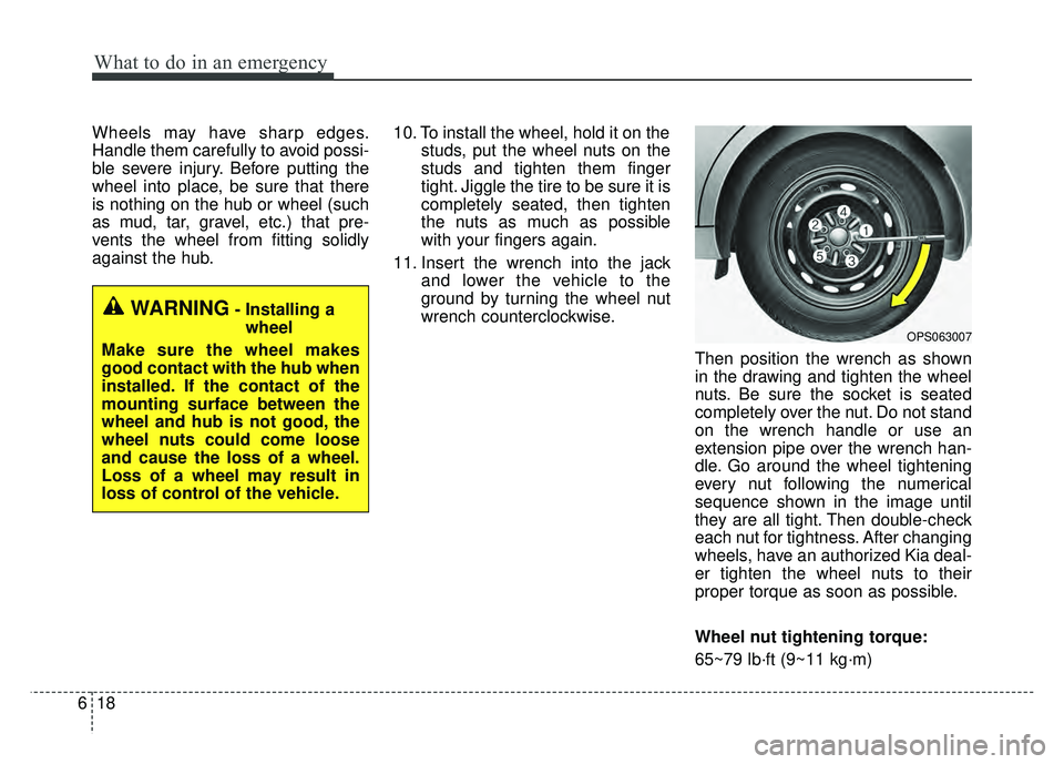
6.Loosen the wheel lug nuts counter-clockwise one turn each, but do
not remove any nut until the tire
has been raised off the ground.
1VQA4023OPS063004
Page 403 of 544
617
What to do in an emergency
7.Place the jack at the front (1) orrear (2) jacking position closest to
the tire you are changing. Place the
jack at the designated locations
under the frame. 8.Insert the jack handle into the jack
and turn it clockwise, raising the
vehicle until the tire just clears the
ground. This measurement is
approximately 1 in. (30 mm).
Before removing the wheel lug
nuts, make sure the vehicle is sta-
ble and that there is no chance for
movement or slippage. 9.Loosen the wheel nuts and remove
them with your fingers. Slide the
wheel off the studs and lay it flat so
it cannot roll away. To put the wheel
on the hub, pick up the spare tire,
line up the holes with the studs and
slide the wheel onto them. If this is
difficult, tip the wheel slightly and
get the top hole in the wheel lined
up with the top stud. Then jiggle the
wheel back and forth until the
wheel can slide over the other
studs.
OAM069009
OPS063006
OPS063005
Page 404 of 544

What to do in an emergency
18
6
Wheels may have sharp edges.
Handle them carefully to avoid possi-
ble severe injury. Before putting the
wheel into place, be sure that there
is nothing on the hub or wheel (such
as mud, tar, gravel, etc.) that pre-
vents the wheel from fitting solidly
against the hub. 10. To install the wheel, hold it on the
studs, put the wheel nuts on the
studs and tighten them finger
tight. Jiggle the tire to be sure it is
completely seated, then tighten
the nuts as much as possible
with your fingers again.
11. Insert the wrench into the jack and lower the vehicle to the
ground by turning the wheel nut
wrench counterclockwise.
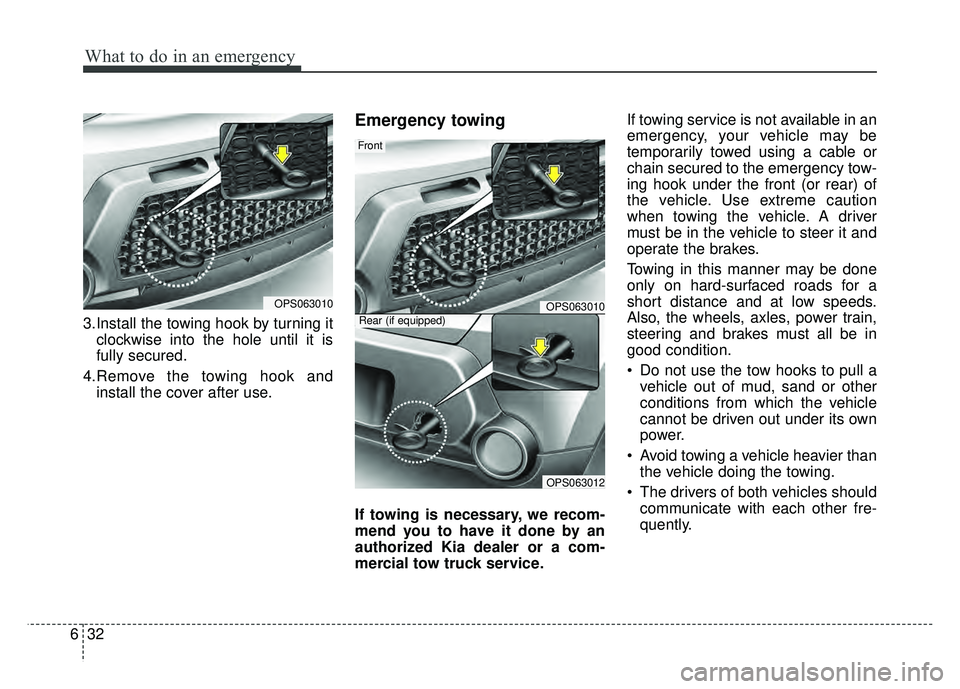
Then position the wrench as shown
in the drawing and tighten the wheel
nuts. Be sure the socket is seated
completely over the nut. Do not stand
on the wrench handle or use an
extension pipe over the wrench han-
dle. Go around the wheel tightening
every nut following the numerical
sequence shown in the image until
they are all tight. Then double-check
each nut for tightness. After changing
wheels, have an authorized Kia deal-
er tighten the wheel nuts to their
proper torque as soon as possible.
Wheel nut tightening torque:
65~79 lb·ft (9~11 kg·m)
WARNING- Installing awheel
Make sure the wheel makes
good contact with the hub when
installed. If the contact of the
mounting surface between the
wheel and hub is not good, the
wheel nuts could come loose
and cause the loss of a wheel.
Loss of a wheel may result in
loss of control of the vehicle.
OPS063007
Page 418 of 544

What to do in an emergency
32
6
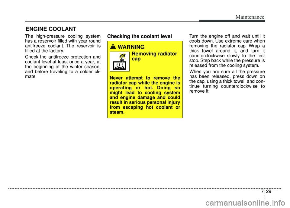
3.Install the towing hook by turning it
clockwise into the hole until it is
fully secured.
4.Remove the towing hook and install the cover after use.
Emergency towing
If towing is necessary, we recom-
mend you to have it done by an
authorized Kia dealer or a com-
mercial tow truck service. If towing service is not available in an
emergency, your vehicle may be
temporarily towed using a cable or
chain secured to the emergency tow-
ing hook under the front (or rear) of
the vehicle. Use extreme caution
when towing the vehicle. A driver
must be in the vehicle to steer it and
operate the brakes.
Towing in this manner may be done
only on hard-surfaced roads for a
short distance and at low speeds.
Also, the wheels, axles, power train,
steering and brakes must all be in
good condition.
Do not use the tow hooks to pull a
vehicle out of mud, sand or other
conditions from which the vehicle
cannot be driven out under its own
power.
Avoid towing a vehicle heavier than the vehicle doing the towing.
The drivers of both vehicles should communicate with each other fre-
quently.
OPS063010OPS063010
OPS063012
Front
Rear (if equipped)
Page 449 of 544

729
Maintenance
ENGINE COOLANT
The high-pressure cooling system
has a reservoir filled with year round
antifreeze coolant. The reservoir is
filled at the factory.
Check the antifreeze protection and
coolant level at least once a year, at
the beginning of the winter season,
and before traveling to a colder cli-
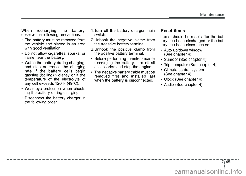
mate.Checking the coolant levelTurn the engine off and wait until it
cools down. Use extreme care when
removing the radiator cap. Wrap a
thick towel around it, and turn it
counterclockwise slowly to the first
stop. Step back while the pressure is
released from the cooling system.
When you are sure all the pressure
has been released, press down on
the cap, using a thick towel, and con-
tinue turning counterclockwise to
remove it.
WARNING
Removing radiator
cap
Never attempt to remove the
radiator cap while the engine is
operating or hot. Doing so
might lead to cooling system
and engine damage and could
result in serious personal injury
from escaping hot coolant or
steam.
Page 465 of 544

745
Maintenance
When recharging the battery,
observe the following precautions:
The battery must be removed fromthe vehicle and placed in an area
with good ventilation.
Do not allow cigarettes, sparks, or flame near the battery.
Watch the battery during charging, and stop or reduce the charging
rate if the battery cells begin
gassing (boiling) violently or if the
temperature of the electrolyte of
any cell exceeds 120°F (49°C).
Wear eye protection when check- ing the battery during charging.
Disconnect the battery charger in the following order. 1.Turn off the battery charger main
switch.
2.Unhook the negative clamp from the negative battery terminal.
3.Unhook the positive clamp from the positive battery terminal.
Before performing maintenance or recharging the battery, turn off all
accessories and stop the engine.
The negative battery cable must be removed first and installed last
when the battery is disconnected.Reset items
Items should be reset after the bat-
tery has been discharged or the bat-
tery has been disconnected.
Auto up/down window (See chapter 4)
Sunroof (See chapter 4)
Trip computer (See chapter 4)
Climate control system (See chapter 4)
Clock (See chapter 4)
Audio (See chapter 4)
Page 483 of 544
763
Maintenance
3. Pull the suspected fuse straightout. Use the fuse puller provided
on the engine compartment fuse
panel cover.
4. Check the removed fuse; replace it if it is blown.
Spare fuses are provided in theengine compartment fuse panel.
5. Push in a new fuse of the same rating, and make sure it fits tightly
in the clips.
If it fits loosely, consult an authorized
Kia dealer.
If you do not have a spare, use a fuse of the same rating from a circuityou may not need for operating thevehicle, such as the power outletfuse.
If the headlights or other electrical
components do not work and the
fuses are OK, check the fuse panel
in the engine compartment. If a fuse
is blown, it must be replaced.
Fuse switch
Always, put the fuse switch at the ON
position.
If you move the switch to the OFF
position, some items such as audio
and digital clock must be reset and
transmitter (or smart key) may not
work properly.
OPS073015
OPS073017
Page 497 of 544
777
Maintenance
1. Turn off the engine and open thehood. Disconnect the negative
battery cable.
2. Disconnect the power connector from the back of the headlight
assembly.
3. Loosen the retaining bolts. 4. Pull out the end of the front
bumper.
5. Remove the headlight assembly from the body of the vehicle.
If you can reach the bulb without
removing the headlight assembly,
you do not need to do step 3,4 and 5.
Headlight bulb (High)
Follow the steps 1 to 5 from the pre-
vious page.
6.Remove the headlight bulb cover by turning it counterclockwise.
7.Disconnect the headlight bulb socket-connector.
OPS073046
OPS073051
OPS073028
OPS073047
OPS073026
■ Type A
■Type B