Page 94 of 407

Features of your vehicle
24
4
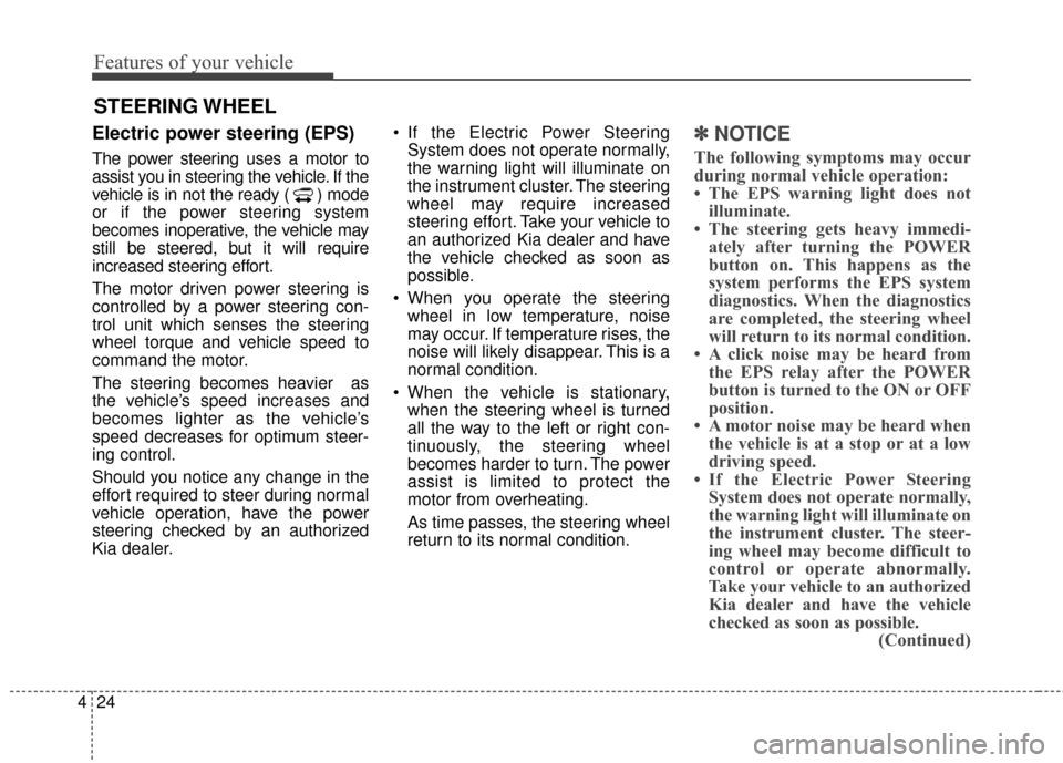
Electric power steering (EPS)
The power steering uses a motor to
assist you in steering the vehicle. If the
vehicle is in not the ready ( ) mode
or if the power steering system
becomes inoperative, the vehicle may
still be steered, but it will require
increased steering effort.
The motor driven power steering is
controlled by a power steering con-
trol unit which senses the steering
wheel torque and vehicle speed to
command the motor.
The steering becomes heavier as
the vehicle’s speed increases and
becomes lighter as the vehicle’s
speed decreases for optimum steer-
ing control.
Should you notice any change in the
effort required to steer during normal
vehicle operation, have the power
steering checked by an authorized
Kia dealer. If the Electric Power Steering
System does not operate normally,
the warning light will illuminate on
the instrument cluster. The steering
wheel may require increased
steering effort. Take your vehicle to
an authorized Kia dealer and have
the vehicle checked as soon as
possible.
When you operate the steering wheel in low temperature, noise
may occur. If temperature rises, the
noise will likely disappear. This is a
normal condition.
When the vehicle is stationary, when the steering wheel is turned
all the way to the left or right con-
tinuously, the steering wheel
becomes harder to turn. The power
assist is limited to protect the
motor from overheating.
As time passes, the steering wheel
return to its normal condition.
✽ ✽ NOTICE
The following symptoms may occur
during normal vehicle operation:
• The EPS warning light does not
illuminate.
• The steering gets heavy immedi- ately after turning the POWER
button on. This happens as the
system performs the EPS system
diagnostics. When the diagnostics
are completed, the steering wheel
will return to its normal condition.
• A click noise may be heard from the EPS relay after the POWER
button is turned to the ON or OFF
position.
• A motor noise may be heard when the vehicle is at a stop or at a low
driving speed.
• If the Electric Power Steering System does not operate normally,
the warning light will illuminate on
the instrument cluster. The steer-
ing wheel may become difficult to
control or operate abnormally.
Take your vehicle to an authorized
Kia dealer and have the vehicle
checked as soon as possible. (Continued)
STEERING WHEEL
Page 311 of 407
Maintenance
48
7
✽
✽
NOTICE
The actual fuse/relay panel label
may differ from equipped items.
Inner panel fuse replacement
1. Turn the ignition switch and all
other switches off.
2. Open the fuse panel cover.
OPSE074006L
CAUTION
Do not use a screwdriver or any other metal object to removefuses because it may cause ashort circuit and damage thesystem.
WARNING- Fuse fire
When replacing a blown fuse or relay with a new one, make
sure the new fuse or relay fits
tightly into the clips The
incomplete fastening fuse or
relay may cause the vehicle
wiring and electric systems
damage and a possible fire.
Do not remove fuses, relays and terminals fastened with
bolts or nuts. The fuses, relays
and terminals may be fastened
incompletely, and it may cause
a possible fire. If fuses, relays
and terminals fastened with
bolts or nuts are blown, we
recommend that you consult
with an authorized Kia dealer.
Page 314 of 407
751
Maintenance
Fuse/relay panel description
Inside the fuse/relay panel covers,
you can find the fuse/relay label
describing fuse/relay name and
capacity.
✽ ✽NOTICE
Not all fuse panel descriptions in
this manual may be applicable to
your vehicle. It is accurate at the
time of printing. When you inspect
the fuse panel in your vehicle, refer
to the fuse panel label.
OPSE074010L
OPSE074028L
Page 315 of 407

Maintenance
52
7
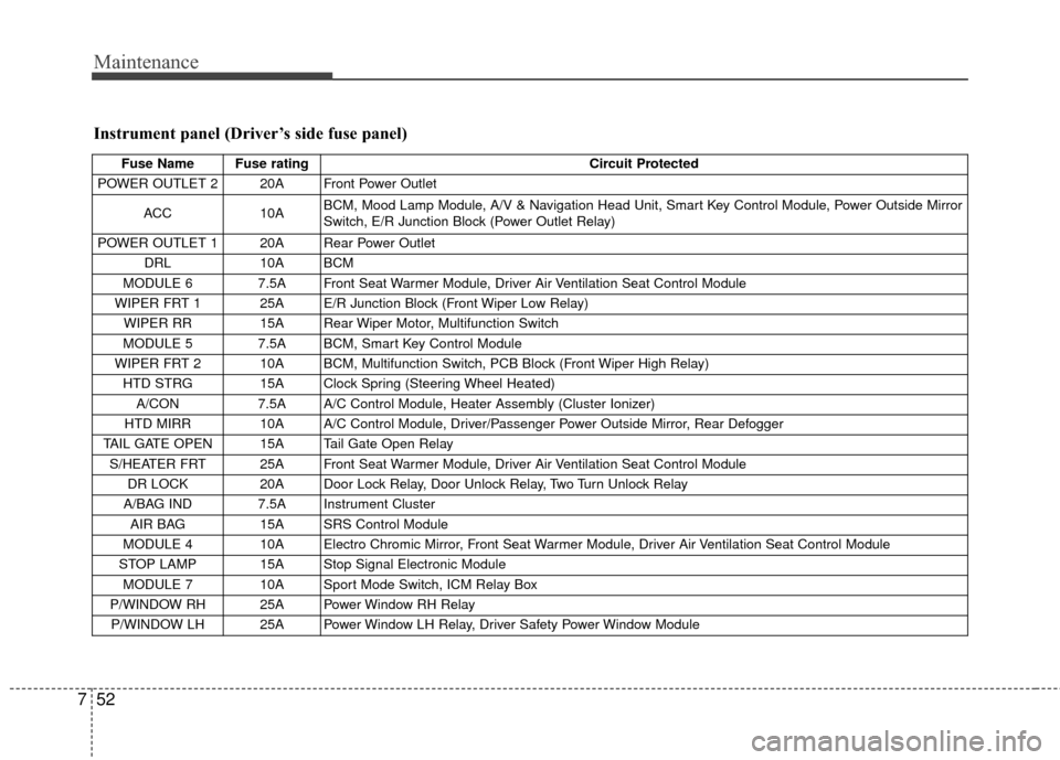
Instrument panel (Driver’s side fuse panel)
Fuse Name Fuse rating Circuit Protected
POWER OUTLET 2 20A Front Power Outlet
ACC 10A BCM, Mood Lamp Module, A/V & Navigation Head Unit, Smart Key Control Module, Power Outside Mirror
Switch, E/R Junction Block (Power Outlet Relay)
POWER OUTLET 1 20A Rear Power Outlet DRL 10A BCM
MODULE 6 7.5A Front Seat Warmer Module, Driver Air Ventilation Seat Control Module
WIPER FRT 1 25A E/R Junction Block (Front Wiper Low Relay) WIPER RR 15A Rear Wiper Motor, Multifunction Switch
MODULE 5 7.5A BCM, Smart Key Control Module
WIPER FRT 2 10A BCM, Multifunction Switch, PCB Block (Front Wiper High Relay) HTD STRG 15A Clock Spring (Steering Wheel Heated) A/CON 7.5A A/C Control Module, Heater Assembly (Cluster Ionizer)
HTD MIRR 10A A/C Control Module, Driver/Passenger Power Outside Mirror, Rear Defogger
TAIL GATE OPEN 15A Tail Gate Open Relay S/HEATER FRT 25A Front Seat Warmer Module, Driver Air Ventilation Seat Control Module DR LOCK 20A Door Lock Relay, Door Unlock Relay, Two Turn Unlock Relay
A/BAG IND 7.5A Instrument Cluster AIR BAG 15A SRS Control Module
MODULE 4 10A Electro Chromic Mirror, Front Seat Warmer Module, Driver Air Ventilation Seat Control Module
STOP LAMP 15A Stop Signal Electronic Module MODULE 7 10A Sport Mode Switch, ICM Relay Box
P/WINDOW RH 25A Power Window RH Relay P/WINDOW LH 25A Power Window LH Relay, Driver Safety Power Window Module
Page 316 of 407

753
Maintenance
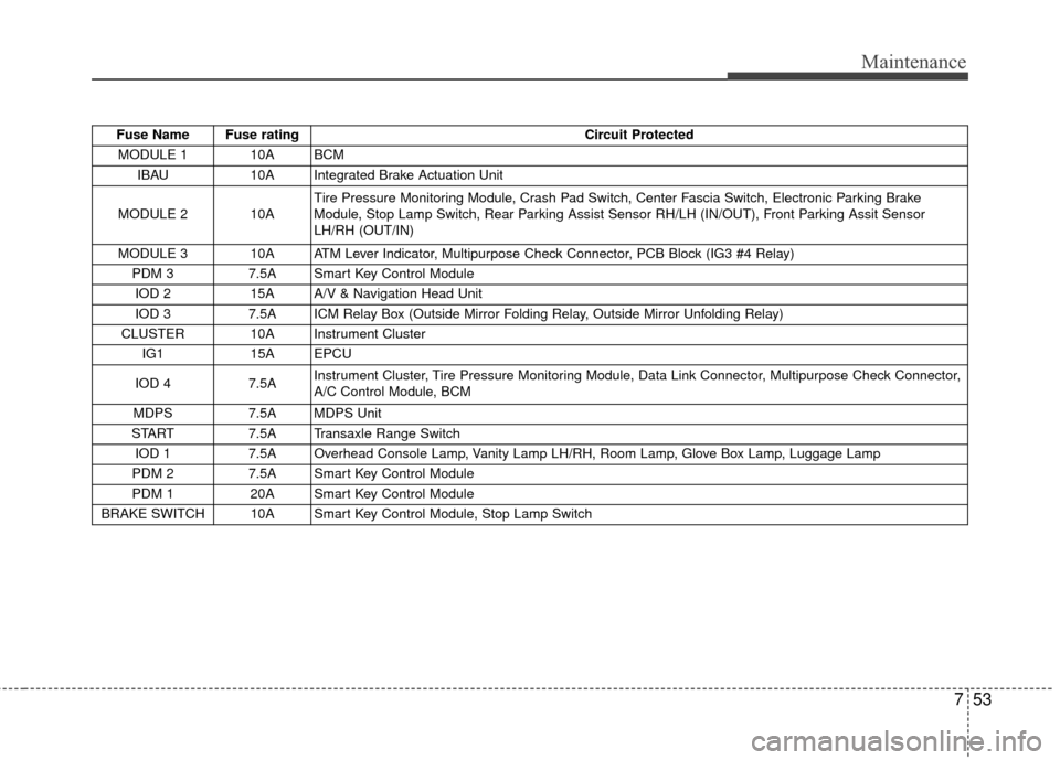
Fuse Name Fuse ratingCircuit Protected
MODULE 1 10A BCM IBAU 10A Integrated Brake Actuation Unit
MODULE 2 10A Tire Pressure Monitoring Module, Crash Pad Switch, Center Fascia Switch, Electronic Parking Brake
Module, Stop Lamp Switch, Rear Parking Assist Sensor RH/LH (IN/OUT), Front Parking Assit Sensor
LH/RH (OUT/IN)
MODULE 3 10A ATM Lever Indicator, Multipurpose Check Connector, PCB Block (IG3 #4 Relay) PDM 3 7.5A Smart Key Control Module
IOD 2 15A A/V & Navigation Head Unit
IOD 3 7.5A ICM Relay Box (Outside Mirror Folding Relay, Outside Mirror Unfolding Relay)
CLUSTER 10A Instrument Cluster IG1 15A EPCU
IOD 4 7.5A Instrument Cluster, Tire Pressure Monitoring Module, Data Link Connector, Multipurpose Check Connector,
A/C Control Module, BCM
MDPS 7.5A MDPS Unit
START 7.5A Transaxle Range Switch
IOD 1 7.5A Overhead Console Lamp, Vanity Lamp LH/RH, Room Lamp, Glove Box Lamp, Luggage Lamp
PDM 2 7.5A Smart Key Control Module
PDM 1 20A Smart Key Control Module
BRAKE SWITCH 10A Smart Key Control Module, Stop Lamp Switch
Page 318 of 407
755
Maintenance
Fuse Name Fuse ratingCircuit Protected
MDPS 80A MDPS Unit
ALT 150A Alternator
B+1 50A Smart Junction Block (Fuse - (S/HEATER FRT, TAIL GATE OPEN, DR LOCK, P/WINDOW LH, P/WINDOW
RH, MODULE 7))
B+2 50A Smart Junction Block (Fuse - (STOP LAMP) Arisu-LT2)
B+3 50A Smart Junction Block (Fuse - (PDM 1, PDM 2, BRAKE SWITCH, Leak Current Autocut Device) IPS1,
Arisu-LT1)
IG2 40A PCB Block (Button Start (IG2) Relay)
POWER OUTLET 20A Power Outlet Relay OBC 10A OBC Unit, Rear Heated Relay
BMS 10A BMS Control Module
EPCU 20A EPCU
CHARGER 2 10A Normal Charge Port Lmap C/FAN 40A COOLING FAN 1 Relay, COOLING FAN 2 Relay
RR HTD 40A Rear Heated Relay IBAU 2 30A Integrated Brake Actuation Unit
IBAU 1 40A Integrated Brake Actuation Unit
Page 319 of 407
Maintenance
56
7
Fuse Name Fuse rating Circuit Protected
IG1 40A Button Start (ACC) Relay, Button Start (IG1) Relay
BLOWER 40A Blower Relay IG3 1 30A IG3 #1/#2/#3/#4/#5 Relay
EPB 1 30A Electronic Parking Brake Module
EPB 2 30A Electronic Parking Brake Module
IG3 2 10A Blower Relay, A/C Control Module, A/C Compressor, E/R Junction Block (Cooling Fan 1/2 Relay), Heater
Assembly (PTC Heater)
CHARGER 1 10A OBC Unit, BMS Control Module EWP 10A Electronic Water Pump
IG3 3 15A EPCU, Transaxle Range Switch, A/V & Navigation Head Unit, Instrument Cluster
HORN 15A Horn Relay
B/UP LAMP 10A Transaxle Range Switch, EPCU
BATTERY C/FAN 25A Battery C/FAN Relay
No. Relay Name Type
E41 Power Outlet Relay PLUG MICRO
E42 C/FAN 1 Relay PLUG MICRO
E43 RR HTD Relay PLUG MICRO
E44 C/FAN 2 Relay PLUG MINI
Page 320 of 407
757
Maintenance
Motor compartment fuse panel(Battery terminal cover)
✽
✽ NOTICE
The actual fuse/relay panel label
may differ from equipped items.
OPSE074015L
OPSE074014