Page 81 of 407
411
Features of your vehicle
DOOR LOCKS
.Operating door locks from
outside the vehicle
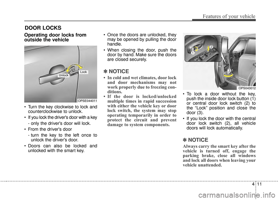
Turn the key clockwise to lock andcounterclockwise to unlock.
If you lock the driver's door with a key
- only the driver's door will lock.
From the driver's door
- turn the key to the left once tounlock the driver's door.
Doors can also be locked and unlocked with the smart key. Once the doors are unlocked, they
may be opened by pulling the door
handle.
When closing the door, push the door by hand. Make sure the doors
are closed securely.
✽ ✽ NOTICE
• In cold and wet climates, door lock
and door mechanisms may not
work properly due to freezing con-
ditions.
• If the door is locked/unlocked multiple times in rapid succession
with either the vehicle key or door
lock switch, the system may stop
operating temporarily in order to
protect the circuit and prevent
damage to system components.
To lock a door without the key,
push the inside door lock button (1)
or central door lock switch (2) to
the “Lock” position and close the
door (3).
If you lock the door with the central door lock switch (2), all vehicle
doors will lock automatically.
✽ ✽ NOTICE
Always carry the smart key after the
vehicle is turned off, engage the
parking brake, close all windows
and lock all doors when leaving your
vehicle unattended.
OPSE044011
LockUnlock
OPS043012
Page 186 of 407
Features of your vehicle
116
4
If you install aftermarket HID head
lamps, your vehicle’s audio and elec-
tronic devices may malfunction.Antenna
Your vehicle uses a roof antenna to
receive AM or/and FM broadcast sig-
nals.
This antenna pole is removable. To
remove the roof antenna pole, turn it
counterclockwise. To install the roof
antenna pole, turn it clockwise. When reinstalling your roof anten-
na pole, it is important that it is fully
tightened to ensure proper recep-
tion.
When cargo is loaded on the roof rack, do not place the cargo near
the antenna pole to ensure proper
reception.
AUDIO SYSTEM
OHM048154N
CAUTION- Antenna
Before entering a place with alow height clearance or a carwash, remove the antenna poleby rotating it counterclockwise.If not, the antenna may be dam-aged.
Page 261 of 407
621
What to do in an emergency
When towing your vehicle in an
emergency without wheel dollies :
1. Set the ignition switch in the ACCposition.
2. Place the transaxle shift lever in N (Neutral).
3. Release the parking brake.Removable towing hook
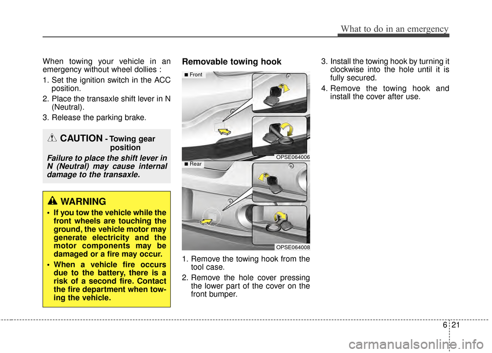
1. Remove the towing hook from the tool case.
2. Remove the hole cover pressing the lower part of the cover on the
front bumper. 3. Install the towing hook by turning it
clockwise into the hole until it is
fully secured.
4. Remove the towing hook and install the cover after use.
CAUTION- Towing gear
position
Failure to place the shift lever inN (Neutral) may cause internaldamage to the transaxle.
WARNING
If you tow the vehicle while the front wheels are touching the
ground, the vehicle motor may
generate electricity and the
motor components may be
damaged or a fire may occur.
When a vehicle fire occurs due to the battery, there is a
risk of a second fire. Contact
the fire department when tow-
ing the vehicle.
OPSE064006
OPSE064008
■Front
■Rear
Page 283 of 407
Maintenance
20
7
COOLANT
The high-pressure cooling system
has a reservoir filled with year round
antifreeze coolant. The reservoir is
filled at the factory.
Check the antifreeze protection and
coolant level at least once a year, at
the beginning of the winter season,
and before traveling to a colder cli-
mate.Checking the coolant levelTurn the vehicle off and wait until it
cools down. Use extreme care when
removing the radiator cap. Wrap a
thick towel around it, and turn it
counterclockwise slowly to the first
stop. Step back while the pressure is
released from the cooling system.
When you are sure all the pressure
has been released, press down on
the cap, using a thick towel, and con-
tinue turning counterclockwise to
remove it.
WARNING
Removing radiator
cap
Never attempt to remove the
radiator cap while the motor
compartment is operating or
hot. Doing so might lead to
cooling system damage and
could result in serious personal
injury from escaping hot
coolant or steam.
Page 312 of 407
749
Maintenance
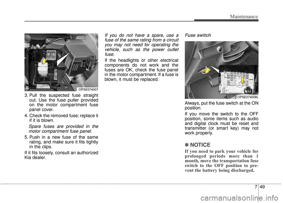
3. Pull the suspected fuse straightout. Use the fuse puller provided
on the motor compartment fuse
panel cover.
4. Check the removed fuse; replace it if it is blown.
Spare fuses are provided in themotor compartment fuse panel.
5. Push in a new fuse of the same rating, and make sure it fits tightly
in the clips.
If it fits loosely, consult an authorized
Kia dealer.
If you do not have a spare, use a fuse of the same rating from a circuityou may not need for operating thevehicle, such as the power outletfuse.
If the headlights or other electrical
components do not work and the
fuses are OK, check the fuse panel
in the motor compartment. If a fuse is
blown, it must be replaced.
Fuse switch
Always, put the fuse switch at the ON
position.
If you move the switch to the OFF
position, some items such as audio
and digital clock must be reset and
transmitter (or smart key) may not
work properly.
✽ ✽ NOTICE
If you need to park your vehicle for
prolonged periods more than 1
month, move the transportation fuse
switch to the OFF position to pre-
vent the battery being discharged.
OPSE074008L
OPSE074007
Page 315 of 407
Maintenance
52
7
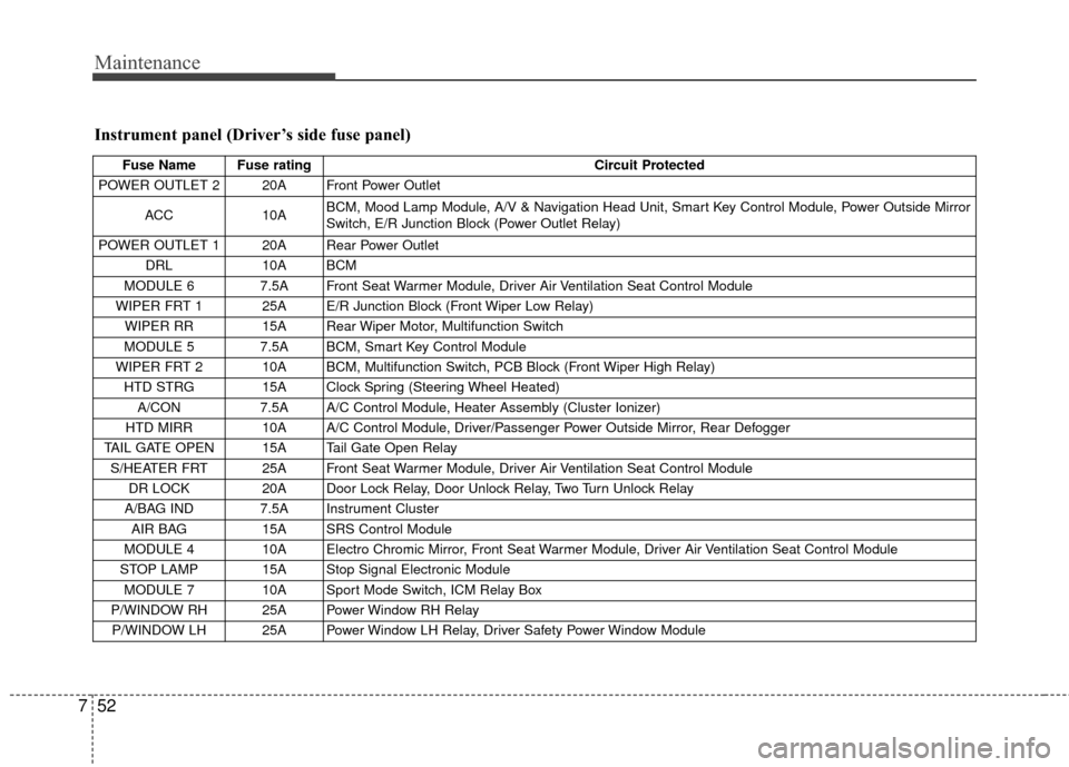
Instrument panel (Driver’s side fuse panel)
Fuse Name Fuse rating Circuit Protected
POWER OUTLET 2 20A Front Power Outlet
ACC 10A BCM, Mood Lamp Module, A/V & Navigation Head Unit, Smart Key Control Module, Power Outside Mirror
Switch, E/R Junction Block (Power Outlet Relay)
POWER OUTLET 1 20A Rear Power Outlet DRL 10A BCM
MODULE 6 7.5A Front Seat Warmer Module, Driver Air Ventilation Seat Control Module
WIPER FRT 1 25A E/R Junction Block (Front Wiper Low Relay) WIPER RR 15A Rear Wiper Motor, Multifunction Switch
MODULE 5 7.5A BCM, Smart Key Control Module
WIPER FRT 2 10A BCM, Multifunction Switch, PCB Block (Front Wiper High Relay) HTD STRG 15A Clock Spring (Steering Wheel Heated) A/CON 7.5A A/C Control Module, Heater Assembly (Cluster Ionizer)
HTD MIRR 10A A/C Control Module, Driver/Passenger Power Outside Mirror, Rear Defogger
TAIL GATE OPEN 15A Tail Gate Open Relay S/HEATER FRT 25A Front Seat Warmer Module, Driver Air Ventilation Seat Control Module DR LOCK 20A Door Lock Relay, Door Unlock Relay, Two Turn Unlock Relay
A/BAG IND 7.5A Instrument Cluster AIR BAG 15A SRS Control Module
MODULE 4 10A Electro Chromic Mirror, Front Seat Warmer Module, Driver Air Ventilation Seat Control Module
STOP LAMP 15A Stop Signal Electronic Module MODULE 7 10A Sport Mode Switch, ICM Relay Box
P/WINDOW RH 25A Power Window RH Relay P/WINDOW LH 25A Power Window LH Relay, Driver Safety Power Window Module
Page 324 of 407
761
Maintenance
Headlight bulb (High, Low)
Follow the steps 1 to 6 from the pre-
vious page.
7. Remove the headlight bulb coverby turning it counterclockwise.
8. Disconnect the headlight bulb socket-connector.
9. Unsnap the headlight bulb retain- ing wire by depressing the end
and pushing it upward.
10. Remove the bulb from the head- light assembly. 11. Install a new headlight bulb and
snap the headlight bulb retaining
wire into position by aligning the
wire with the groove on the bulb.
12. Connect the headlight bulb sock- et connector.
13. Install the headlight bulb cover by turning it clockwise.
14. Connect the power connector to the back of the headlight assem-
bly.
15. Reinstall the headlight assembly to the body of the vehicle.
Front turn signal / position light /
DRL
LED type
If the light bulb is not operating, have
the vehicle checked by an authorized
Kia dealer.
OPSE074031L
High Low
OPSE074017
Position
light/DRL
Turn signal light
Page 325 of 407
Maintenance
62
7
Front side marker
Follow the steps 1 to 6 from the pre-
vious page.
7.Remove the socket from the
assembly by turning the socket
counterclockwise until the tabs on
the socket align with the slots on
the assembly.
8.Pull the bulb out of the socket.
9.Insert a new bulb into the socket.
10. Install the socket into the assem- bly by aligning the tabs on the
socket with the slots on the
assembly and turning the socket
clockwise.
Front fog lamp bulbs (if equipped)
1. Remove the front bumper undercover.
2. Reach your hand into the back of the front bumper. 3. Disconnect the power connector
from the socket.
4. Remove the bulb-socket from the housing by turning the socket
counter clockwise until the tabs on
the socket align with the slots on
the housing.
5. Install the new bulb-socket into the housing by aligning the tabs on
the socket with the slots in the
housing. Push the socket into the
housing and turn the socket clock-
wise.
6. Connect the power connector to the socket.
7. Reinstall the front bumper under cover.
✽ ✽NOTICE
If the headlight aiming adjustment
is necessary after the headlight
assembly is reinstalled, consult an
authorized Kia dealer.
OPS073028
OPSE074029L
OPS073025