Page 1148 of 1210
785
Maintenance
FuseFuse ratingSymbolFuse NameProtected component
FUSE
15ADEICERICM Relay Box (Front Deicer Relay)
15ASTOP
LAMPSTOP LAMPStop Signal Electronic Relay , HAC RELAY
20A5TCU1TCU
40ADCT1DCT1TCU (DCT)
40A7EMSEMS Box (FUSE No. - 1/2/3/4/5/6/7/8/9)
50AB+3B+3Inner Fuse Panel (Leak Current Autocut Device, Fuse No. - 6/19/20/17/32/26/25)
50ABLOWERBLOWER RELAY
10AA/CONA/C Control Module
10AWIPER FRTECU, Rain Sensor
10AB/UP
LAMPB/UP LPM/T : Back-up Lamp Switch, A/T : Transaxle Range Switch, TCU
15A4ECU4Smart Key Control Module, Immobiliser Module, ECU
10A3ABS3ESC Control Module, ABS Control Module, Yaw Rate Sensor, HAC, ESS RELAY
15A6TCU2Transaxle Range Switch, TCU, Stop Lamp Switch
JD RHD 7.QXP 4/14/2015 6:31 PM Page 85
Page 1150 of 1210
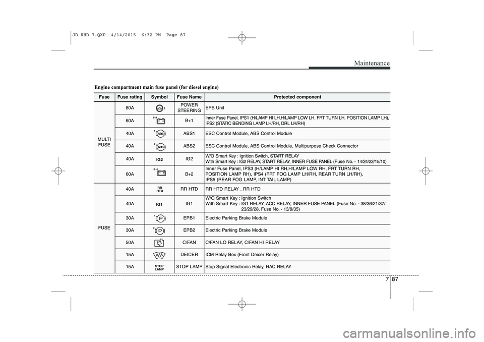
787
Maintenance
FuseFuse ratingSymbolFuse NameProtected component
MULTIFUSE
80A1POWER
STEERINGEPS Unit
60AB+1B+1Inner Fuse Panel, IPS1 (H/LAMP HI LH,H/LAMP LOW LH, FRT TURN LH, POSITION LAMP LH),
IPS2 (STATIC BENDING LAMP LH/RH, DRL LH/RH)
40A1ABS1ESC Control Module, ABS Control Module
40A2ABS2ESC Control Module, ABS Control Module, Multipurpose Check Connector
40AIG2IG2W/O Smart Key : Ignition Switch, START RELAYWith Smart Key : IG2 RELAY, START RELAY, INNER FUSE PANEL (Fuse No. - 14/24/22/15/10)
60AB+2B+2Inner Fuse Panel, IPS3 (H/LAMP HI RH,H/LAMP LOW RH, FRT TURN RH,
POSITION LAMP RH), IPS4 (FRT FOG LAMP LH/RH, REAR TURN LH/RH),
IPS5 (REAR FOG LAMP, INT TAIL LAMP)
FUSE
40ARR
HTDRR HTDRR HTD RELAY , RR HTD
40AIG1IG1W/O Smart Key : Ignition Switch
With Smart Key : IG1 RELAY, ACC RELAY, INNER FUSE PANEL ( Fuse No. - 38/36/21/37/
23/29/28, Fuse No. - 13/8/35)
30A1EPB1Electric Parking Brake Module
30A2EPB2Electric Parking Brake Module
50AC/FANC/FAN LO RELAY, C/FAN HI RELAY
15ADEICERICM Relay Box (Front Deicer Relay)
15ASTOP
LAMPSTOP LAMPStop Signal Electronic Relay, HAC RELAY
Engine compartment main fuse panel (for diesel engine)
JD RHD 7.QXP 4/14/2015 6:32 PM Page 87
Page 1151 of 1210
Maintenance
88
7
FuseFuse ratingSymbolFuse NameProtected component
FUSE
20A5TCU1TCU
40AFUEL
HEATERFUEL HEATER RELAY
40A7EMSEMS BOX (Fuse No. - 1/2/3/4/5/6/7/8/9)
50AB+3B+3Inner Fuse Panel (Leak Current Autocut Device, Fuse No. - 6/19/20/17/32/26/25)
50ABLOWERBLOWER RELAY
10AA/CONA/C Control Module
10AWIPER FRTECU, Rain Sensor
10AB/UP
LAMPB/UP LPM/T : Back-up Lamp Switch, A/T : Transaxle Range Switch, TCU
15A4ECU4Smart Key Control Module, Immobiliser Module, ECU, Air Flow Sensor,
Fuel Water Sensor
10A3ABS3ESC Control Module, ABS Control Module, Yaw Rate Sensor, HAC, ESS RELAY
15A6TCU2Transaxle Range Switch, TCU
JD RHD 7.QXP 4/14/2015 6:32 PM Page 88
Page 1157 of 1210
Maintenance
94
7
13. Connect the headlight bulb socket
connector.
14. Install the headlight bulb cover by turning it clockwise.
15. Connect the power connector to the back of the headlight assembly.
Position light (3, bulb type)
Follow the steps 1 to 9 from the previous
page.
10. Pull out the socket from the assembly.
11. Pull the bulb out of the socket.
12. Insert a new bulb into the socket.
13. Install the socket into the assembly.
14. Install the headlight bulb cover byturning it clockwise.
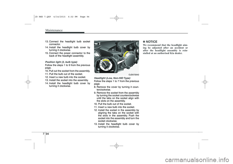
Headlight (Low, Non-HID Type)
Follow the steps 1 to 7 from the previous
page.
8. Remove the cover by turning it coun-terclockwise.
9. Remove the socket from the assembly by turning the socket counterclockwise
until the tabs on the socket align with
the slots on the assembly.
10. Pull the bulb out of the socket.
11. Insert a new bulb into the socket.
12. Install the socket in the assembly by aligning the tabs on the socket with
the slots in the assembly. Push the
socket into the assembly and turn the
socket clockwise.
13. Install the headlight bulb cover by turning it clockwise.
✽✽NOTICE
We recommend that the headlight aim-
ing be adjusted after an accident or
after the headlight assembly is rein-
stalled at an authorised Kia dealer.
OJD072042
JD RHD 7.QXP 4/14/2015 6:32 PM Page 94
Page 1159 of 1210
Maintenance
96
7
Turn signal light
Follow the steps 1 to 7 from the previous
page.
8. Remove the socket from the assembly
by turning the socket counterclockwise
until the tabs on the socket align with
the slots on the assembly.
9. Remove the bulb from the socket by pressing it in and rotating it counter-
clockwise until the tabs on the bulb
align with the slots in the socket. Pull
the bulb out of the socket.
10. Insert a new bulb by inserting it into the socket and rotating it until it locks
into place. 11. Install the socket in the assembly by
aligning the tabs on the socket with
the slots in the assembly. Push the
socket into the assembly and turn the
socket clockwise.
Front fog light, Daytime running light
(if equipped)
1. Pull the wheel guard down by rotating the screws.
2. Reach your hand into the back of the front bumper.
3. Disconnect the power connector from the socket.
OJD072044OJD072050
JD RHD 7.QXP 4/14/2015 6:32 PM Page 96
Page 1160 of 1210
797
Maintenance
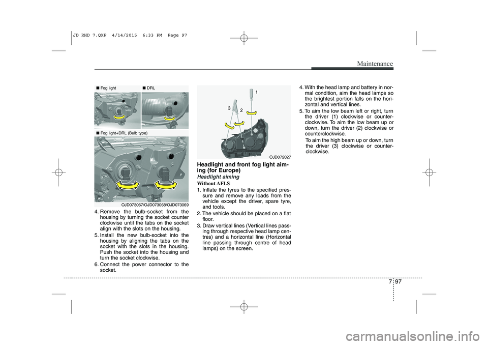
4. Remove the bulb-socket from thehousing by turning the socket counter
clockwise until the tabs on the socketalign with the slots on the housing.
5. Install the new bulb-socket into the housing by aligning the tabs on the
socket with the slots in the housing.
Push the socket into the housing and
turn the socket clockwise.
6. Connect the power connector to the socket. Headlight and front fog light aim-
ing (for Europe)
Headlight aiming
Without AFLS
1. Inflate the tyres to the specified pres-
sure and remove any loads from the
vehicle except the driver, spare tyre,
and tools.
2. The vehicle should be placed on a flat floor.
3. Draw vertical lines (Vertical lines pass- ing through respective head lamp cen-
tres) and a horizontal line (Horizontalline passing through centre of headlamps) on the screen. 4. With the head lamp and battery in nor-
mal condition, aim the head lamps so
the brightest portion falls on the hori-
zontal and vertical lines.
5. To aim the low beam left or right, turn the driver (1) clockwise or counter-
clockwise. To aim the low beam up or
down, turn the driver (2) clockwise or
counterclockwise.
To aim the high beam up or down, turnthe driver (3) clockwise or counter-
clockwise.
OJD072027
■ Fog light
■Fog light+DRL (Bulb type) ■
DRL
OJD073067/OJD073068/OJD073069
JD RHD 7.QXP 4/14/2015 6:33 PM Page 97
Page 1169 of 1210
Maintenance
106
7
❈ The actual rear combination lamp shape in
the vehicle may differ from illustration.
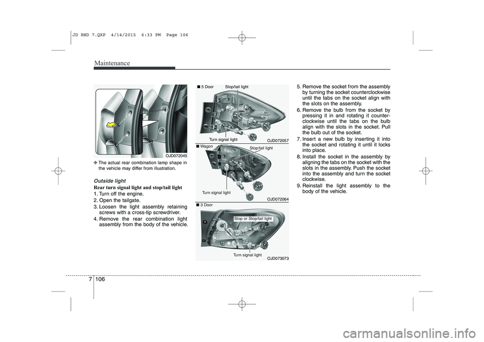
Outside light
Rear turn signal light and stop/tail light
1. Turn off the engine.
2. Open the tailgate.
3. Loosen the light assembly retaining
screws with a cross-tip screwdriver.
4. Remove the rear combination light assembly from the body of the vehicle. 5. Remove the socket from the assembly
by turning the socket counterclockwise
until the tabs on the socket align with
the slots on the assembly.
6. Remove the bulb from the socket by pressing it in and rotating it counter-
clockwise until the tabs on the bulb
align with the slots in the socket. Pull
the bulb out of the socket.
7. Insert a new bulb by inserting it into the socket and rotating it until it locks
into place.
8. Install the socket in the assembly by aligning the tabs on the socket with the
slots in the assembly. Push the socket
into the assembly and turn the socket
clockwise.
9. Reinstall the light assembly to the body of the vehicle.
OJD072045
OJD072057
OJD072064
■
5 Door
■Wagon
OJD073073
■ 3 Door
Turn signal light
Stop/tail light
Stop or Stop/tail light
Turn signal light
Stop/tail light
Turn signal light
JD RHD 7.QXP 4/14/2015 6:33 PM Page 106
Page 1171 of 1210
Maintenance
108
7
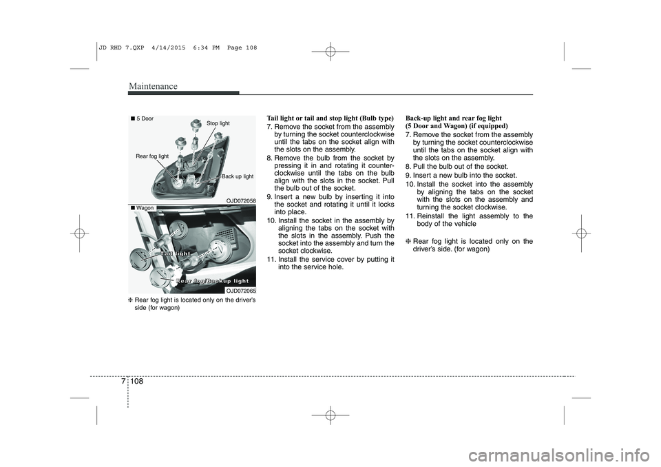
❈ Rear fog light is located only on the driver’s
side (for wagon) Tail light or tail and stop light (Bulb type)
7. Remove the socket from the assembly
by turning the socket counterclockwise
until the tabs on the socket align with
the slots on the assembly.
8. Remove the bulb from the socket by pressing it in and rotating it counter-
clockwise until the tabs on the bulb
align with the slots in the socket. Pull
the bulb out of the socket.
9. Insert a new bulb by inserting it into the socket and rotating it until it locks
into place.
10. Install the socket in the assembly by aligning the tabs on the socket with
the slots in the assembly. Push the
socket into the assembly and turn the
socket clockwise.
11. Install the service cover by putting it into the service hole. Back-up light and rear fog light
(5 Door and Wagon) (if equipped)
7. Remove the socket from the assembly
by turning the socket counterclockwise
until the tabs on the socket align with
the slots on the assembly.
8. Pull the bulb out of the socket.
9. Insert a new bulb into the socket.
10. Install the socket into the assembly by aligning the tabs on the socket
with the slots on the assembly and
turning the socket clockwise.
11. Reinstall the light assembly to the body of the vehicle
❈ Rear fog light is located only on the
driver’s side. (for wagon)
OJD072058
■5 Door
■Wagon
Rear fog light
Back up light
Stop light
OJD072065
RRRReeeeaaaarrrr ffffoooogggg////BBBBaaaacccckkkkuuuupppp lllliiiigggghhhhtttt
TTTTaaaaiiiillll lllliiiigggghhhhtttt
JD RHD 7.QXP 4/14/2015 6:34 PM Page 108