2015 KIA CEED ABS
[x] Cancel search: ABSPage 1025 of 1210
575
Driving your vehicle
Parking on hills
Generally, if you have a trailer attached to
your vehicle, you should not park your
vehicle on a hill. People can be seriously
or fatally injured, and both your vehicle
and the trailer can be damaged if unex-
pectedly roll down hill.However, if you ever have to park your
trailer on a hill, here is how to do it:
1. Pull the vehicle into the parking space.
Turn the steering wheel in the direction
of the kerb (left if headed down hill,
right if headed up hill).
2. If the vehicle has a manual transaxle, place the car in neutral. If the vehicle
has an automatic transaxle, place the
car in P (Park).
3. Set the parking brake and shut off the vehicle.
4. Place chocks under the trailer wheels on the down hill side of the wheels.
5. Start the vehicle, hold the brakes, shift to neutral, release the parking brake
and slowly release the brakes until the
trailer chocks absorb the load.
6. Reapply the brakes, reapply the park- ing brake and shift the vehicle to R
(Reverse) for manual transaxle or P
(Park) for automatic transaxle.
7. Shut off the vehicle and release the vehicle brakes but leave the parking
brake set.
WARNING - Parking on a
hill
Parking your vehicle on a hill with a
trailer attached could cause seri-
ous injury or death, should the trail-
er break loose.
WARNING - Parking brake
It can be dangerous to get out of
your vehicle if the parking brake is
not firmly set.
If you have left the engine running,
the vehicle can move suddenly. You
or others could be seriously or
fatally injured.
JD RHD 5.QXP 2/17/2015 10:35 AM Page 75
Page 1036 of 1210
What to do in an emergency
6
6
Jump starting procedure ✽✽
NOTICE
If the battery is discharged, the engine
can be started using a battery of anoth-
er vehicle and two jumper cables. Only
use jumper cables with fully insulated
clamp handles.
To prevent personal injury or damage to
both vehicles, adhere strictly to the fol-
lowing procedure.
1. Make sure the booster battery is 12- volt and that its negative terminal is
grounded.
2. If the booster battery is in another vehicle, do not allow the vehicles totouch.
3. Turn off all unnecessary electrical loads. 4. Connect the jumper cables in the exact
sequence shown in the illustration.First connect one end of a jumper
cable to the positive terminal of the
discharged battery (1), then connect
the other end to the positive terminal
on the booster battery (2). Proceed toconnect one end of the other jumper
cable to the negative terminal of the
booster battery (3), then the other end
to a solid, stationary, metallic point (for
example, the engine lifting bracket)
away from the battery (4). Do not con-
nect it to or near any part that moves
when the engine is cranked. Make
sure that there is no contact between
the bodywork of the two vehicles; oth-
erwise, there is the danger of short cir-
cuits.
Do not allow the jumper cables to con-
tact anything except the correct battery
terminals or the correct ground. Do not
lean over the battery when making
connections.
CAUTION - Battery cables
Do not connect the jumper cable from
the negative terminal of the booster battery to the negative terminal of thedischarged battery. This can cause
the discharged battery to overheatand crack, releasing battery acid.
CAUTION -AGM battery (if equipped)
Absorbent Glass Matt (AGM) bat-
teries are maintenance-free andwe recommend that the AGM bat-
teries be serviced by an autho-rised Kia dealer. For chargingyour AGM battery, use only fully
automatic battery chargers thatare specially developed for AGMbatteries.
When replacing the AGM battery, we recommend that you use parts
for replacement from an autho-rised Kia dealer.
Do not open or remove the cap on top of the battery. This may cause
leaks of internal electrolyte thatcould result in severe injury.
If the AGM battery is reconnected or replaced, ISG function will notoperate immediately.
If you want to use the ISG func-tion, the battery sensor needs to be calibrated for approximately 4hours with the ignition off.
JD RHD 6.QXP 2/17/2015 11:15 AM Page 6
Page 1042 of 1210
What to do in an emergency
12
6
7. Place the jack at the front (1) or
rear (2) jacking position closest to
the tyre you are changing. Place
the jack at the designated loca-
tions under the frame. The jacking
positions are plates welded to the
frame with two tabs and a raised
dot to index with the jack. 8. Insert the jack handle into the jack
and turn it clockwise, raising the
vehicle until the tyre just clears the
ground. This measurement is
approximately 30 mm (1.2 in).
Before removing the wheel lug
nuts, make sure the vehicle is sta-
ble and that there is no chance for
movement or slippage. 9. Loosen the wheel nuts and
remove them with your fingers.Slide the wheel off the studs and
lay it flat so it cannot roll away. To
put the wheel on the hub, pick up
the spare tyre, line up the holeswith the studs and slide the wheel
onto them. If this is difficult, tip thewheel slightly and get the top holein the wheel lined up with the top
stud. Then jiggle the wheel back
and forth until the wheel can be
slid over the other studs.
WARNING - Jack location
To reduce the possibility of
injury, be sure to use only the
jack provided with the vehicle
and in the correct jack position;
never use any other part of the
vehicle for jack support.
OJD062005OVG063015/Q
JD RHD 6.QXP 2/17/2015 11:15 AM Page 12
Page 1124 of 1210
761
Maintenance
Compact spare tyre replacement (if equipped)
A compact spare tyre has a shorter
tread life than a regular size tyre.
Replace it when you can see the
tread wear indicator bars on the tyre.The replacement compact spare tyre
should be the same size and design
tyre as the one provided with your
new vehicle and should be mountedon the same compact spare tyre
wheel. The compact spare tyre is notdesigned to be mounted on a regular
size wheel, and the compact spare
tyre wheel is not designed for mount-
ing a regular size tyre.
WARNING - Replacing
tyres
Driving on worn-out tyres is very hazardous and will
reduce braking effectiveness,
steering accuracy, and trac-tion.
Your vehicle is equipped with tyres designed to provide for
safe ride and handling capa-
bility. Do not use a size andtype of tyre and wheel that is
different from the one that is
originally installed on your
vehicle. It can affect the safety
and performance of your vehi-
cle, which could lead to han-
dling failure or rollover and
serious injury. When replacing
the tyres, be sure to equip all
four tyres with the tyre and
wheel of the same size, type,
tread, brand and load-carrying
capacity.
(Continued)(Continued)
The use of any other tyre sizeor type may seriously affect
ride, handling, ground clear-
ance, stopping distance, body
to tyre clearance, snow tyre
clearance, and speedometer
reliability.
It is best to replace all four tyres at the same time. If that
is not possible, or necessary,
then replace the two front or
two rear tyres as a pair.Replacing just one tyre can
seriously affect your vehicle’shandling.
The ABS works by comparing the speed of the wheels. Tyre
size can affect wheel speed.
When replacing tyres, all 4
tyres must use the same size
originally supplied with the
vehicle. Using tyres of a dif-
ferent size can cause the ABS
(Anti-lock Brake System) and
ESC (Electronic Stability
Control) to work irregularly.
JD RHD 7.QXP 4/14/2015 6:30 PM Page 61
Page 1138 of 1210
775
Maintenance
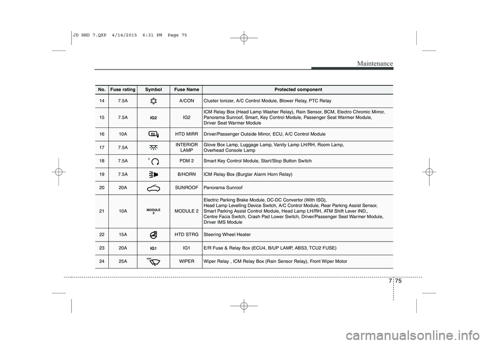
No.Fuse ratingSymbolFuse NameProtected component
147.5AA/CONCluster Ionizer, A/C Control Module, Blower Relay, PTC Relay
157.5AIG2IG2ICM Relay Box (Head Lamp Washer Relay), Rain Sensor, BCM, Electro Chromic Mirror,
Panorama Sunroof, Smart, Key Control Module, Passenger Seat Warmer Module,
Driver Seat Warmer Module
1610AHTD MIRRDriver/Passenger Outside Mirror, ECU, A/C Control Module
177.5AINTERIORLAMPGlove Box Lamp, Luggage Lamp, Vanity Lamp LH/RH, Room Lamp,
Overhead Console Lamp
187.5A2PDM 2Smart Key Control Module, Start/Stop Button Switch
197.5AB/HORNICM Relay Box (Burglar Alarm Horn Relay)
2020ASUNROOFPanorama Sunroof
2110AMODULE 2MODULE 2
Electric Parking Brake Module, DC-DC Convertor (With ISG),
Head Lamp Levelling Device Switch, A/C Control Module, Rear Parking Assist Sensor,
Smart Parking Assist Control Module, Head Lamp LH/RH, ATM Shift Lever IND.,
Centre Facia Switch, Crash Pad Lower Switch, Driver/Passenger Seat Warmer Module,
Driver IMS Module
2215AHTD STRGSteering Wheel Heater
2320AIG1IG1E/R Fuse & Relay Box (ECU4, B/UP LAMP, ABS3, TCU2 FUSE)
2425AFRTWIPERWiper Relay , ICM Relay Box (Rain Sensor Relay), Front Wiper Motor
JD RHD 7.QXP 4/14/2015 6:31 PM Page 75
Page 1144 of 1210
781
Maintenance
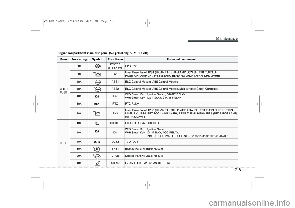
Fuse Fuse ratingSymbolFuse NameProtected component
MULTIFUSE
80A1POWER
STEERINGEPS Unit
60AB+1B+1Inner Fuse Panel, IPS1 (H/LAMP HI LH,H/LAMP LOW LH, FRT TURN LH,
POSITION LAMP LH), IPS2 (STATIC BENDING LAMP LH/RH, DRL LH/RH)
40A1ABS1ESC Control Module, ABS Control Module
40A2ABS2ESC Control Module, ABS Control Module, Multipurpose Check Connector
40AIG2IG2W/O Smart Key : Ignition Switch, START RELAY
With Smart Key : IG2 RELAY, START RELAY
60APTCPTCPTC Relay
60AB+2B+2Inner Fuse Panel, IPS3 (H/LAMP HI RH,H/LAMP LOW RH, FRT TURN RH,POSITION
LAMP RH), IPS4 (FRT FOG LAMP LH/RH, REAR TURN LH/RH), IPS5 (REAR FOG LAMP,
INT TAIL LAMP)
FUSE
40ARR
HTDRR HTDRR HTD RELAY , RR HTD
40AIG1IG1W/O Smart Key : Ignition Switch
With Smart Key : IG1 RELAY, ACC RELAY,
INNER FUSE PANEL (FUSE No. - 8/13/21/23/28/29/35/36/37/38)
40ADCT2DCT2TCU (DCT)
30A1EPB1Electric Parking Brake Module
30A2EPB2Electric Parking Brake Module
40AC/FANC/FAN LO RELAY, C/FAN HI RELAY
Engine compartment main fuse panel (for petrol engine MPI, GDI)
JD RHD 7.QXP 4/14/2015 6:31 PM Page 81
Page 1145 of 1210
Maintenance
82
7
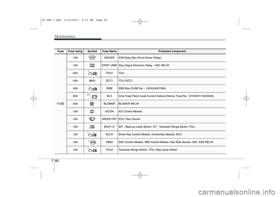
FuseFuse ratingSymbolFuse NameProtected component
FUSE
15ADEICERICM Relay Box (Front Deicer Relay)
15ASTOP
LAMPSTOP LAMPStop Signal Electronic Relay , HAC RELAY
20A5TCU1TCU
40ADCT1DCT1TCU (DCT)
40A7EMSEMS Box (FUSE No. - 1/2/3/4/5/6/7/8/9)
50AB+3B+3Inner Fuse Panel (Leak Current Autocut Device, Fuse No. - 6/19/20/17/32/26/25)
50ABLOWERBLOWER RELAY
10AA/CONA/C Control Module
10AWIPER FRTECU, Rain Sensor
10AB/UP
LAMPB/UP LPM/T : Back-up Lamp Switch, A/T : Transaxle Range Switch, TCU
15A4ECU4Smart Key Control Module, Immobiliser Module, ECU
10A3ABS3ESC Control Module, ABS Control Module, Yaw Rate Sensor, HAC, ESS RELAY
15A6TCU2Transaxle Range Switch, TCU, Stop Lamp Switch
JD RHD 7.QXP 4/14/2015 6:31 PM Page 82
Page 1147 of 1210
Maintenance
84
7
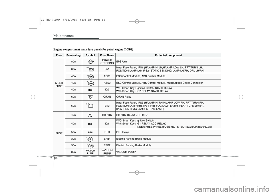
Fuse Fuse ratingSymbolFuse NameProtected component
MULTI
FUSE
80A1POWER
STEERINGEPS Unit
60AB+1B+1Inner Fuse Panel, IPS1 (H/LAMP HI LH,H/LAMP LOW LH, FRT TURN LH,
POSITION LAMP LH), IPS2 (STATIC BENDING LAMP LH/RH, DRL LH/RH)
40A1ABS1ESC Control Module, ABS Control Module
40A2ABS2ESC Control Module, ABS Control Module, Multipurpose Check Connector
40AIG2IG2W/O Smart Key : Ignition Switch, START RELAY
With Smart Key : IG2 RELAY, START RELAY
60AC/FANC/FAN Relay
60AB+2B+2Inner Fuse Panel, IPS3 (H/LAMP HI RH,H/LAMP LOW RH, FRT TURN RH, POSITION LAMP RH), IPS4 (FRT FOG LAMP LH/RH, REAR TURN LH/RH),
IPS5 (REAR FOG LAMP, INT TAIL LAMP)
FUSE
40ARR
HTDRR HTDRR HTD RELAY , RR HTD
40AIG1IG1W/O Smart Key : Ignition Switch
With Smart Key : IG1 RELAY, ACC RELAY,
INNER FUSE PANEL (FUSE No. - 8/13/21/23/28/29/35/36/37/38)
50APTCPTCPTC Relay
30A1EPB1Electric Parking Brake Module
30A2EPB2Electric Parking Brake Module
30AVACUUMPUMPVACUUM
PUMPVACUUM PUMP
Engine compartment main fuse panel (for petrol engine T-GDI)
JD RHD 7.QXP 4/14/2015 6:31 PM Page 84