Page 466 of 678
Mounting Fuse Cover and Locking Screw
Proceed as follows:
•Properly secure the fuse cover to the box, slide com-
pletely from top to bottom.
•Fully depress the screw, using the special screwdriver
supplied.
•Slowly turn the screw clockwise.
•Release the screw.
Battery Fuse Cover Location
1—FuseCoverTabs2—FuseCover
464 IN CASE OF EMERGENCY
Page 470 of 678
Cavity Maxi FuseMini FuseMicro Fuse Description
F84——30 Amp Green Power Supply All
Wheel Drive
F87——5 Amp Tan Shift Lever Automatic
Transmission
F88——7.5 Amp Brown Heated Outside
Mirrors
F89——30 Amp Green Heated Rear Window
F90——5 Amp Tan IBS Sensor (Battery
State of Charge)
Body Computer Fuse Center
The controller is located at the left side of the steering
column at the bottom of the instrument panel.
468 IN CASE OF EMERGENCY
Page 473 of 678
CavityMini FuseDescription
Dome, Mirror, Electric Motor Retractable
Roof, Heated Front Seats, Stabilizer Battery,
ESC System, ESL
F507.5 Amp BrownSupply Air Bag
F517.5 Amp BrownAlarm Power, Front Courtesy Light, Air
Conditioning Compressor, Brake Pedal
Switch (NC), Plaque Automatic Transmis-
sion, Compass, Rear Camera, Leveling
Headlights, Air Conditioning
F537.5 Amp BrownSupply IPC/Starter Device/System Keyless
Enter-N-Go™
F9415 Amp BluePower Socket
8
IN CASE OF EMERGENCY 471
Page 494 of 678

WARNING!
Store the sealant canister in its special compartment,
away from sources of heat.
JUMP-STARTING PROCEDURES
If your vehicle has a discharged battery it can be jump-
started using a set of jumper cables and a battery in
another vehicle or by using a portable battery booster
pack. Jump-starting can be dangerous if done improperly
so please follow the procedures in this section carefully.
NOTE:When using a portable battery booster pack
follow the manufacturer ’s operating instructions and
precautions.
CAUTION!
Do not use a portable battery booster pack or any
other booster source with a system voltage greater
than 12 Volts or damage to the battery, starter motor,
alternator or electrical system may occur.
WARNING!
Do not attempt jump-starting if the battery is frozen.
It could rupture or explode and cause personal injury.
Preparations For Jump-Start
The battery in your vehicle is located in the front of the
engine compartment, behind the left headlight assembly.
NOTE:The positive battery post is covered with a
protective cap. Lift up on the cap to gain access to the
positive battery post.
492 IN CASE OF EMERGENCY
Page 495 of 678

WARNING!
•Take care to avoid the radiator cooling fan when-
ever the hood is raised. It can start anytime the
ignition switch is ON. You can be injured by
moving fan blades.
•Remove any metal jewelry such as rings, watch
bands and bracelets that could make an inadvertent
electrical contact. You could be seriously injured.
•Batteries contain sulfuric acid that can burn your
skin or eyes and generate hydrogen gas which is
flammable and explosive. Keep open flames or
sparks away from the battery.
Proceed as follows:
1. Set the Electric Park Brake, shift the automatic trans-
mission into PARK (manual transmission in NEU-
TRAL) and turn the ignition to STOP/OFF.
2. Turn off the heater, radio, and all unnecessary electri-
cal accessories.
3. If using another vehicle to jump-start the battery, park
the vehicle within the jumper cables reach, set the
parking brake and make sure the ignition is STOP/
OFF.
WARNING!
Do not allow vehicles to touch each other as this
could establish a ground connection and personal
injury could result.
8
IN CASE OF EMERGENCY 493
Page 496 of 678

Jump-Starting Procedure
WARNING!
Failure to follow this jump-starting procedure could
result in personal injury or property damage due to
battery explosion.
CAUTION!
Failure to follow these procedures could result in
damage to the charging system of the booster vehicle
or the discharged vehicle.
Connecting The Jumper Cables
1. Connect the positive(+)end of the jumper cable to the
positive(+)post of the discharged vehicle.
2. Connect the opposite end of the positive(+)jumper
cable to the positive(+)post of the booster battery.
3. Connect the negative(-)end of the jumper cable to the
negative(-)post of the booster battery.
4. Connect the opposite end of the negative(-)jumper
cable to a good engine ground (exposed metal part of
the discharged vehicle’s engine) away from the battery
and the fuel injection system.
WARNING!
Do not connect the jumper cable to the negative (-)
post of the discharged battery. The resulting electri-
cal spark could cause the battery to explode and
could result in personal injury. Only use the specific
ground point, do not use any other exposed metal
parts.
494 IN CASE OF EMERGENCY
Page 497 of 678

5. Start the engine in the vehicle that has the booster
battery, let the engine idle a few minutes, and then
start the engine in the vehicle with the discharged
battery.
6. Once the engine is started, remove the jumper cables
in the reverse sequence:
Disconnecting The Jumper Cables
1. Disconnect the negative(-)end of the jumper cable
from the engine ground of the vehicle with the dis-
charged battery.
2. Disconnect the opposite end of the negative(-)jumper
cable from the negative(-)post of the booster battery.
3. Disconnect the positive(+)end of the jumper cable
from the positive(+)post of the booster battery.
4. Disconnect the opposite end of the positive(+)jumper
cable from the positive(+)post of the vehicle with the
discharged battery.
If frequent jump-starting is required to start your vehicle
you should have the battery and charging system in-
spected at your authorized dealer.
CAUTION!
Accessories plugged into the vehicle power outlets
draw power from the vehicle’s battery, even when not
in use (i.e., cellular phones, etc.). Eventually, if
plugged in long enough without engine operation,
the vehicle’s battery will discharge sufficiently to
degrade battery life and/or prevent the engine from
starting.
8
IN CASE OF EMERGENCY 495
Page 498 of 678
ENHANCED ACCIDENT RESPONSE SYSTEM
In the event of an impact, if the communication network
remains intact, and the power remains intact, depending
on the nature of the event, the ORC will determine
whether to have the Enhanced Accident Response Sys-
tem perform the following functions:
•Cut off fuel to the engine.
•Flash hazard lights as long as the battery has power or
until the ignition switch is turned to the STOP/OFF
position.
•Turn on the interior lights, which remain on as long as
the battery has power or until the ignition switch is
turned to the STOP/OFF position.
•Unlock the doors automatically.
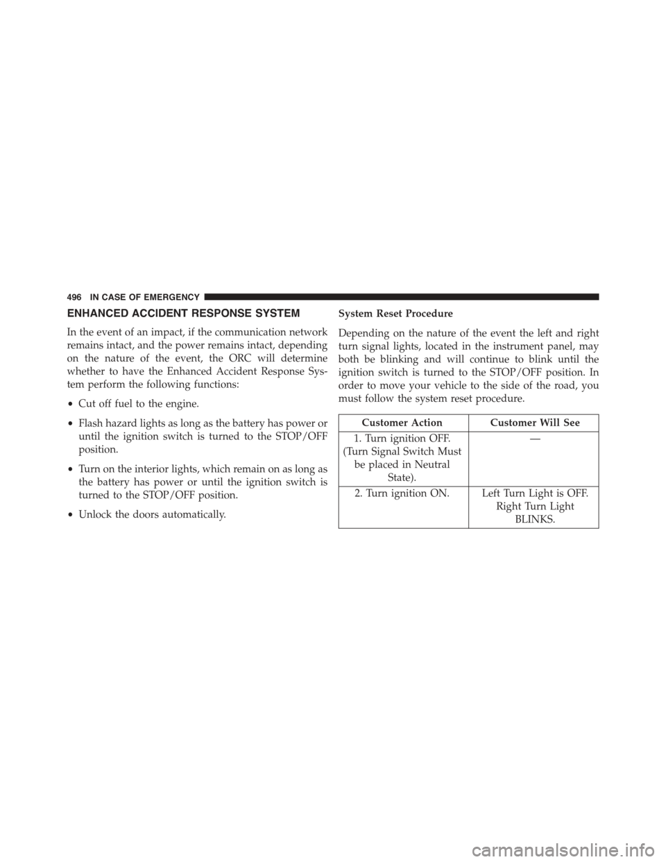
System Reset Procedure
Depending on the nature of the event the left and right
turn signal lights, located in the instrument panel, may
both be blinking and will continue to blink until the
ignition switch is turned to the STOP/OFF position. In
order to move your vehicle to the side of the road, you
must follow the system reset procedure.
Customer Action Customer Will See
1. Turn ignition OFF.
(Turn Signal Switch Must
be placed in Neutral
State).
—
2. Turn ignition ON. Left Turn Light is OFF.
Right Turn Light
BLINKS.
496 IN CASE OF EMERGENCY


