Page 48 of 132
• Pushing the AUX button will change the mode to auxiliary device if the Audio Jack
is connected, allowing the music from your portable device to play through the
vehicle's speakers.
The functions of the portable device are controlled using the device buttons, not the
buttons on the radio. However, the volume may be controlled using the radio or
portable device.
Uconnect® 430/430N
Uconnect® 430/430N
1 — Voice Command Button2 — Open/Close Display3 — Menu Button4 — Audio Settings Button5 — Internal Hard Drive Button6 — USB Port
7 — Audio Jack8 — Radio Sales Code9 — ON/OFF/Rotate For Volume10 — Select Media Mode Button11 — Radio Mode Button12 — Uconnect®Phone Button
ELECTRONICS
46
Page 53 of 132

Push the MEDIA button on the faceplate to display the media source tabs at the top
of the screen. Select the source by pressing the “HDD,” “DISC,” or “AUX” media
source button on the touchscreen tab.
NOTE:
Your Touchscreen Radio will automatically switch to the appropriate mode when
something is first connected or inserted into the system.
Insert a CD/DVD Disc
• To insert a disc, push the LOAD button on the faceplate.
• With the printed side upwards, insert the disc into the disc slot of the radio. The
radio pulls the disc in automatically and closes the flip screen. The radio selects
the appropriate mode after the disc is recognized, and starts playing the first track.
The display shows “Reading...” during this process.
Seek Up/Seek Down
• Push the “Seek Up” or “Seek Down” buttons on the touchscreen to seek through
tracks in Disc Mode. Hold either Seek button to bypass tracks without stopping.
Audio Jack Operation
The AUX/Audio Jack provides a means to connect a portable audio device, such as an
MP3 player or an iPod®, to the vehicle’s sound system. This requires the use of a
3.5 mm stereo audio patch cable.
•Push the MEDIA button on the faceplate then the “AUX” button on the touchscreen
to change the mode to auxiliary device if the Audio Jack is connected, allowing the
music from your portable device to play through the vehicle's speakers.
NOTE:
The functions of the portable device are controlled using the device itself, not the
buttons on the radio. However, the volume may be controlled using the radio or
portable device.
Hard Disk Drive (HDD) Operation
• The Hard Disk Drive (HDD) mode gives you access to the audio files on the internal
hard disk drive. It functions similar to a CD player, with the exception that the
internal HDD can hold more tracks.
• It is also possible to import display pictures to the internal hard disk drive. The
pictures can be displayed on the right half of the radio screen.
• Before using the HDD mode, you will need to copy songs and pictures to the
internal hard drive. Songs and pictures can be added to the hard drive by using a
CD or USB device (e.g. thumb drive or memory stick).
NOTE:
• HDD supports only .jpg/JPEG formats for photos.
• WMA/MP3 Files and Selective Songs from a CD can also be added to the HDD. See
the Uconnect®430/430N User's Manual for more information.
ELECTRONICS
51
Page 90 of 132

AUTOMATIC TRANSMISSION OVERHEATING
During sustained high speed driving or trailer towing up long grades on hot days, the
automatic transmission oil may become too hot.
When the transmission overheat warning lightturns on, you will experience
reduced performance until the automatic transmission cools down. Once the trans-
mission has cooled down and the light turns off, you may continue to drive normally.
If the high speed is maintained, the overheating will continue to occur.
If the overheating continues, it may become necessary to stop the vehicle and run the
engine at idle with the transmission in NEUTRAL until the light turns off.
JACKING AND TIRE CHANGING
Jack Location
The jack and jack-handle are stowed under the load floor in the cargo area.
Spare Tire Stowage
The compact spare tire is stowed under
the rear load floor in the cargo area.
Spare Tire Removal
• Lift up the load floor cover and remove
the hold down.
Preparations For Jacking
1. Park the vehicle on a firm level surface, avoiding ice or slippery areas.
2. Turn on the Hazard Warning flasher.
3. Set the parking brake.
4. Place the shift lever in PARK (automatic transmission) or REVERSE (manual
transmission).
5. Turn OFF the ignition.
Spare/Jack/Tools
1 — Spare Tire2 — Jack And Tools
WHAT TO DO IN EMERGENCIES
88
Page 91 of 132
6. Block both the front and rear of the wheel diagonally opposite the jacking
position. For example, if changing the right front tire, block the left rear wheel.
NOTE:
Passengers should not remain in the ve-
hicle while the vehicle is being jacked.
Jacking Instructions
NOTE:
Refer to “Tires — General Information”
in “Starting And Operating” in the Own-
er's Manual on the DVD for further infor-
mation about the spare tire, it's use, and
operation.
1. Remove the scissors jack and lug
wrench from the spare wheel as an
assembly. Turn the jack screw to the
left to loosen the lug wrench and re-
move the wrench from the jack as-
sembly.
Wheel Blocked
Warning Label
WHAT TO DO IN EMERGENCIES
89
Page 92 of 132

2. Loosen, but do not remove, the wheel nuts by turning them to the left one turn
while the wheel is still on the ground.
NOTE:
• There are front and rear jacking locations on each side of the body. The front
locations are outlined by two triangular cutouts, the rear locations by two
rectangular cutouts.
• For vehicles equipped with plastic
trim, the plastic has been cut away
to expose the jacking locations in
the body.
• Do not raise the vehicle until you are
sure the jack is securely engaged.
3. Turn the jack screw to the left until the
jack can be placed under the jacking
location. Once the jack is positioned,
turn the jack screw to the right until
the jack head is properly engaged with
the lift area closest to the wheel to be
changed.
4. Using the swivel wrench raise the ve-
hicle by turning the jack screw to the
right. Raise the vehicle only until the
tire just clears the surface and enough
clearance is obtained to install the
spare tire. Minimum tire lift provides
maximum stability.
Front Jack Engaged
Rear Jack Engaged
WHAT TO DO IN EMERGENCIES
90
Page 93 of 132

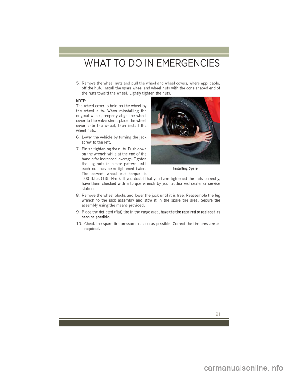
5. Remove the wheel nuts and pull the wheel and wheel covers, where applicable,
off the hub. Install the spare wheel and wheel nuts with the cone shaped end of
the nuts toward the wheel. Lightly tighten the nuts.
NOTE:
The wheel cover is held on the wheel by
the wheel nuts. When reinstalling the
original wheel, properly align the wheel
cover to the valve stem, place the wheel
cover onto the wheel, then install the
wheel nuts.
6. Lower the vehicle by turning the jack
screw to the left.
7. Finish tightening the nuts. Push down
on the wrench while at the end of the
handle for increased leverage. Tighten
the lug nuts in a star pattern until
each nut has been tightened twice.
The correct wheel nut torque is
100 ft/lbs (135 N·m). If you doubt that you have tightened the nuts correctly,
have them checked with a torque wrench by your authorized dealer or service
station.
8. Remove the wheel blocks and lower the jack until it is free. Reassemble the lug
wrench to the jack assembly and stow it in the spare tire area. Secure the
assembly using the means provided.
9. Place the deflated (flat) tire in the cargo area,have the tire repaired or replaced as
soon as possible.
10. Check the spare tire pressure as soon as possible. Correct the tire pressure as
required.
Installing Spare
WHAT TO DO IN EMERGENCIES
91
Page 94 of 132

Road Tire Installation
Vehicles Equipped With Wheel Covers
1. Mount the road tire on the axle.
2. To ease the installation process for steel wheels with wheel covers, install two lug
nuts on the mounting studs which are on each side of the valve stem. Install the
lug nuts with the cone shaped end of the nut toward the wheel. Lightly tighten the
lug nuts.
3. Align the valve notch in the wheel
cover with the valve stem on the
wheel. Install the cover by hand,
snapping the cover over the two lug
nuts. Do not use a hammer or exces-
sive force to install the cover.
4. Install the remaining lug nuts with the
cone shaped end of the nut toward the
wheel. Lightly tighten the lug nuts.
5. Lower the vehicle to the ground by
turning the jack handle counterclock-
wise.
6. Finish tightening the lug nuts. Push
down on the wrench while at the end
of the handle for increased leverage.
Tighten the lug nuts in a star pattern
until each nut has been tightened
twice. The correct tightness of each
lug nut is 100 ft/lbs (135 N·m). If in doubt about the correct tightness, have them
checked with a torque wrench by your authorized dealer or service station.
7. After 25 miles (40 km) check the lug nut torque with a torque wrench to ensure
that all lug nuts are properly seated against the wheel.
Wheel Cover Installation
1 — Valve Stem2 — Valve Notch3 — Wheel Lug Nut4 — Wheel Cover5 — Mounting Stud
WHAT TO DO IN EMERGENCIES
92
Page 95 of 132

Vehicles Without Wheel Covers
1. Mount the road tire on the axle.
2. Install the remaining lug nuts with the cone shaped end of the nut toward the
wheel. Lightly tighten the lug nuts.
3. Lower the vehicle to the ground by turning the jack handle counterclockwise.
4. Finish tightening the lug nuts. Push down on the wrench while at the end of the
handle for increased leverage. Tighten the lug nuts in a star pattern until each nut
has been tightened twice. The correct tightness of each lug nut is 100 ft/lbs
(135 N·m). If in doubt about the correct tightness, have them checked with a
torque wrench by your authorized dealer or service station.
5. After 25 miles (40 km) check the lug nut torque with a torque wrench to ensure
that all lug nuts are properly seated against the wheel.
CAUTION!
• Do not attempt to raise the vehicle by jacking on locations other than those
indicated in the Jacking Instructions for this vehicle.
• Be sure to mount the spare tire with the valve stem facing outward. The vehicle
could be damaged if the spare tire is mounted incorrectly.
WHAT TO DO IN EMERGENCIES
93