Page 256 of 636
Sunroof Maintenance
Use only a nonabrasive cleaner and a soft cloth to clean
the glass panel.
Ignition Off Operation
NOTE:
•The power sunroof switch can remain active for up to
approximately ten minutes after the vehicles ignition is
placed to the Off position. Opening either front door
will cancel this feature.
•This feature is programmable using the Uconnect®
System. Refer to “Uconnect® Settings” in “Under-
standing Your Instrument Panel” for further informa-
tion.
COMMANDVIEW® SUNROOF WITH POWER
SHADE — IF EQUIPPED
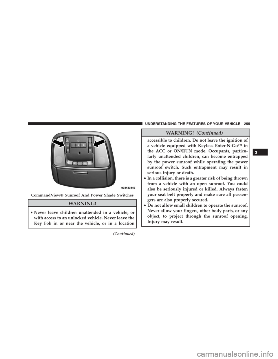
The CommandView® sunroof switch is located to the left
between the sun visors on the overhead console.
The power shade switch is located to the right between
the sun visors on the overhead console.
254 UNDERSTANDING THE FEATURES OF YOUR VEHICLE
Page 257 of 636

WARNING!
•Never leave children unattended in a vehicle, or
with access to an unlocked vehicle. Never leave the
Key Fob in or near the vehicle, or in a location
(Continued)
WARNING!(Continued)
accessible to children. Do not leave the ignition of
a vehicle equipped with Keyless Enter-N-Go™ in
the ACC or ON/RUN mode. Occupants, particu-
larly unattended children, can become entrapped
by the power sunroof while operating the power
sunroof switch. Such entrapment may result in
serious injury or death.
•In a collision, there is a greater risk of being thrown
from a vehicle with an open sunroof. You could
also be seriously injured or killed. Always fasten
your seat belt properly and make sure all passen-
gers are also properly secured.
•Do not allow small children to operate the sunroof.
Never allow your fingers, other body parts, or any
object, to project through the sunroof opening.
Injury may result.
CommandView® Sunroof And Power Shade Switches
3
UNDERSTANDING THE FEATURES OF YOUR VEHICLE 255
Page 261 of 636

Ignition Off Operation
NOTE:
•The power sunroof switch can remain active for up to
approximately ten minutes after the vehicles ignition is
placed to the Off position. Opening either front door
will cancel this feature.
•This feature is programmable using the Uconnect®
System. Refer to “Uconnect® Settings” in “Under-
standing Your Instrument Panel” for further informa-
tion.
ELECTRICAL POWER OUTLETS
Your vehicle is equipped with 12 Volt (13 Amp) power
outlets that can be used to power cellular phones, small
electronics and other low powered electrical accessories.
The power outlets are labeled with either a “key” or a
“battery” symbol to indicate how the outlet is powered.
Power outlets labeled with a “key” are powered whenthe ignition is in the ON or ACC position, while the
outlets labeled with a “battery” are connected directly to
the battery and powered at all times.
NOTE:
•All accessories connected to the “battery” powered
outlets should be removed or turned off when the
vehicle is not in use to protect the battery against
discharge.
•To ensure proper cigar lighter operation, a MOPAR®
knob and element must be used.
CAUTION!
Power outlets are designed for accessory plugs only.
Do not insert any other object in the power outlets as
this will damage the outlet and blow the fuse.
Improper use of the power outlet can cause damage
not covered by your New Vehicle Limited Warranty.
3
UNDERSTANDING THE FEATURES OF YOUR VEHICLE 259
Page 263 of 636
NOTE:The rear power outlet can be switched from
switched “ignition” only to constant “battery” powered
all the time. See your local authorized dealer for details.
Rear Power OutletPower Outlet Right Rear Quarter Panel Fuse
3
UNDERSTANDING THE FEATURES OF YOUR VEHICLE 261
Page 279 of 636

release of the switch, the wipers will resume the continu-
ous rear wiper operation. When this rotary control is in
the OFF position, rotating it downward will activate the
rear washer pump which will continue to operate as long
as the switch is held. Once the switch is released it will
return to the OFF position and the wipers will cycle
several times before returning to the parked position.
NOTE:As a protective measure, the pump will stop if the
switch is held for more than 20 seconds. Once the switch
is released the pump will resume normal operation.
If the rear wiper is operating when the ignition is turned
OFF, the wiper will automatically return to the “park”
position.
Rear Window Defroster
The rear window defroster button is located on
the climate control panel. Push this button to turn
on the rear window defroster and the heated outsidemirrors (if equipped). An indicator in the button will
illuminate when the rear window defroster is on. The
rear window defroster automatically turns off after ap-
proximately 10 minutes. For an additional five minutes of
operation, push the button a second time.
NOTE:To prevent excessive battery drain, use the rear
window defroster only when the engine is operating.
CAUTION!
Failure to follow these cautions can cause damage to
the heating elements:
•Use care when washing the inside of the rear
window. Do not use abrasive window cleaners on
the interior surface of the window. Use a soft cloth
and a mild washing solution, wiping parallel to the
heating elements. Labels can be peeled off after
soaking with warm water.
(Continued)
3
UNDERSTANDING THE FEATURES OF YOUR VEHICLE 277
Page 286 of 636
INSTRUMENT PANEL FEATURES
1 — Air Outlet 6 — Lower Switch Bank 11 — Hood Release
2 — Instrument Cluster 7 — Hazard Switch 12 — Fuel Door Release
3 — Radio 8 — Storage Bin (SD Card, AUX, USB Me-
dia Hub)13 — Headlight Switch
4 — Glove Compartment 9 — ESC Button 14 — Dimmer Control
5 — Climate Controls 10 — Ignition Switch 284 UNDERSTANDING YOUR INSTRUMENT PANEL
Page 288 of 636

INSTRUMENT CLUSTER DESCRIPTIONS
1. Tachometer
Indicates the engine speed in revolutions per minute
(RPM x 1000).
2. Seat Belt Reminder Light
When the ignition switch is first turned to the
ON/RUN position, this light will turn on for four
to eight seconds as a bulb check. During the bulb
check, if the driver’s seat belt is unbuckled, a chime will
sound. After the bulb check or when driving, if the driver
or front passenger seat belt remains unbuckled, the Seat
Belt Indicator Light will flash or remain on continuously.
Refer to “Occupant Restraints” in “Things To Know
Before Starting Your Vehicle” for further information.3. Anti-Lock Brake (ABS) Light
This light monitors the Anti-Lock Brake System
(ABS). The light will turn on when the ignition
switch is turned to the ON/RUN position and
may stay on for as long as four seconds.
If the ABS light remains on or turns on while driving, it
indicates that the Anti-Lock portion of the brake system
is not functioning and that service is required. However,
the conventional brake system will continue to operate
normally if the BRAKE warning light is not on.
If the ABS light is on, the brake system should be serviced
as soon as possible to restore the benefits of Anti-Lock
brakes. If the ABS light does not turn on when the
ignition switch is turned to the ON/RUN position, have
the light inspected by an authorized dealer.
4. High Beam Indicator
Indicates that headlights are on high beam.
286 UNDERSTANDING YOUR INSTRUMENT PANEL
Page 292 of 636

has been corrected. If the problem is related to the brake
booster, the ABS pump will run when applying the brake
and a brake pedal pulsation may be felt during each stop.
The dual brake system provides a reserve braking capac-
ity in the event of a failure to a portion of the hydraulic
system. A leak in either half of the dual brake system is
indicated by the Brake Warning Light, which will turn on
when the brake fluid level in the master cylinder has
dropped below a specified level.
The light will remain on until the cause is corrected.
NOTE:The light may flash momentarily during sharp
cornering maneuvers, which change fluid level condi-
tions. The vehicle should have service performed, and
the brake fluid level checked.
If brake failure is indicated, immediate repair is neces-
sary.WARNING!
Driving a vehicle with the red brake light on is
dangerous. Part of the brake system may have failed.
It will take longer to stop the vehicle. You could have
a collision. Have the vehicle checked immediately.
Vehicles equipped with the Anti-Lock Brake System
(ABS), are also equipped with Electronic Brake Force
Distribution (EBD). In the event of an EBD failure, the
Brake Warning Light will turn on along with the ABS
Light. Immediate repair to the ABS system is required.
Operation of the Brake Warning Light can be checked by
turning the ignition switch from the OFF position to the
ON/RUN position. The light should illuminate for ap-
proximately two seconds. The light should then turn off
unless the parking brake is applied or a brake fault is
detected. If the light does not illuminate, have the light
inspected by an authorized dealer.
290 UNDERSTANDING YOUR INSTRUMENT PANEL