Page 260 of 636

sunroof position. During Express Vent operation, any
movement of the switch will stop the sunroof.
NOTE:If the sunshade is in the closed position when the
vent switch is pushed, the sunshade will automatically
cycle to the halfway open position prior to the sunroof
opening to the Vent position.
Pinch Protect Feature
This feature will detect an obstruction in the opening of
the sunroof during Express Close operation. If an ob-
struction in the path of the sunroof is detected, the
sunroof will automatically retract. Remove the obstruc-
tion if this occurs. Next, push the switch forward and
release to Express Close.
NOTE:If three consecutive sunroof close attempts result
in Pinch Protect reversals, the fourth close attempt will be
a Manual Close movement with Pinch Protect disabled.
Wind Buffeting
Wind buffeting can be described as the perception of
pressure on the ears or a helicopter-type sound in the
ears. Your vehicle may exhibit wind buffeting with the
windows down, or the sunroof (if equipped) in certain
open or partially open positions. This is a normal occur-
rence and can be minimized. If the buffeting occurs with
the rear windows open, open the front and rear windows
together to minimize the buffeting. If the buffeting occurs
with the sunroof open, adjust the sunroof opening to
minimize the buffeting or open any window.
Sunroof Maintenance
Use only a non-abrasive cleaner and a soft cloth to clean
the glass panel.
258 UNDERSTANDING THE FEATURES OF YOUR VEHICLE
Page 284 of 636

�Uconnect® REAR SEAT ENTERTAINMENT (RSE)
SYSTEM — IF EQUIPPED................341
▫Getting Started.......................341
▫Dual Video Screen.....................343
▫Blu-ray™ Disc Player...................343
▫Play Video Games.....................346
▫Play A DVD/Blu-ray™ Disc Using The
Touchscreen Radio.....................347
▫Important Notes For Dual Video Screen
System.............................350
▫Blu-ray™ Disc Player Remote Control — If
Equipped...........................351
▫Replacing The Remote Control Batteries......352
▫Headphones Operation.................353▫Controls............................354
▫Replacing The Headphone Batteries.........355
▫Unwired® Stereo Headphone Lifetime Limited
Warranty...........................355
�STEERING WHEEL AUDIO CONTROLS — IF
EQUIPPED...........................362
▫Radio Operation......................363
▫CD Player...........................363
�CD/DVD DISC MAINTENANCE...........363
�RADIO OPERATION AND MOBILE PHONES . .364
▫Regulatory And Safety Information.........364
�CLIMATE CONTROLS...................366
▫General Overview.....................367
▫Climate Control Functions...............372
282 UNDERSTANDING YOUR INSTRUMENT PANEL
Page 293 of 636

The light also will turn on when the parking brake is
applied with the ignition switch in the ON/RUN posi-
tion.
NOTE:This light shows only that the parking brake is
applied. It does not show the degree of brake application.
13. Fuel Gauge/Fuel Door Reminder
The fuel pump symbol points to the side of the vehicle
where the fuel door is located. The pointer shows the
level of fuel in the fuel tank when the ignition switch is in
the ON/RUN position.
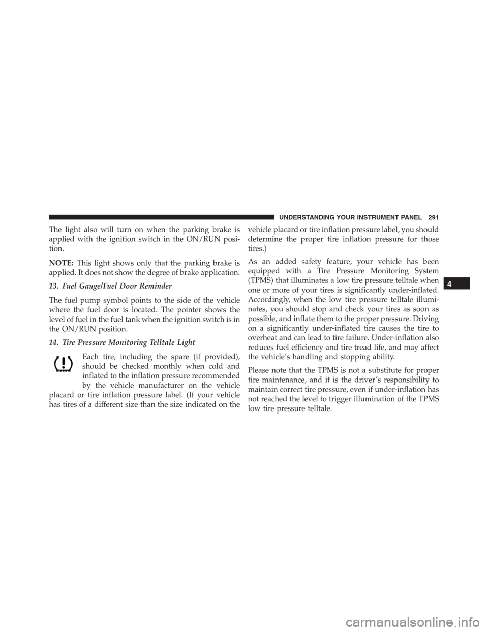
14. Tire Pressure Monitoring Telltale Light
Each tire, including the spare (if provided),
should be checked monthly when cold and
inflated to the inflation pressure recommended
by the vehicle manufacturer on the vehicle
placard or tire inflation pressure label. (If your vehicle
has tires of a different size than the size indicated on thevehicle placard or tire inflation pressure label, you should
determine the proper tire inflation pressure for those
tires.)
As an added safety feature, your vehicle has been
equipped with a Tire Pressure Monitoring System
(TPMS) that illuminates a low tire pressure telltale when
one or more of your tires is significantly under-inflated.
Accordingly, when the low tire pressure telltale illumi-
nates, you should stop and check your tires as soon as
possible, and inflate them to the proper pressure. Driving
on a significantly under-inflated tire causes the tire to
overheat and can lead to tire failure. Under-inflation also
reduces fuel efficiency and tire tread life, and may affect
the vehicle’s handling and stopping ability.
Please note that the TPMS is not a substitute for proper
tire maintenance, and it is the driver ’s responsibility to
maintain correct tire pressure, even if under-inflation has
not reached the level to trigger illumination of the TPMS
low tire pressure telltale.
4
UNDERSTANDING YOUR INSTRUMENT PANEL 291
Page 301 of 636

seconds and then returns to the previous screen. An
example of this message type is “Automatic High Beams
On.”
Engine Oil Life Reset
Oil Change Required
Your vehicle is equipped with an engine oil change
indicator system. The “Oil Change Required” message
will display in the DID for five seconds after a single
chime has sounded, to indicate the next scheduled oil
change interval. The engine oil change indicator system
is duty cycle based, which means the engine oil change
interval may fluctuate, dependent upon your personal
driving style.
Unless reset, this message will continue to display each
time you cycle the ignition to the ON/RUN position. To
turn off the message temporarily, push and release theOK button. To reset the oil change indicator system (after
performing the scheduled maintenance), refer to the
following procedure.
Oil Change Reset Procedure
1. Without pushing the brake pedal, push and release the
ENGINE START/STOP button and place the ignition
to the ON/RUN position (do not start the engine).
2. Fully push the accelerator pedal, slowly, three times
within 10 seconds.
3. Without pushing the brake pedal, push and release the
ENGINE START/STOP button once to return the
ignition to the OFF/LOCK position.
NOTE:If the indicator message illuminates when you
start the vehicle, the oil change indicator system did not
reset. If necessary, repeat this procedure.4
UNDERSTANDING YOUR INSTRUMENT PANEL 299
Page 365 of 636

The right-hand control is a rocker-type switch with a
push-button in the center and controls the volume and
mode of the sound system. Pushing the top of the rocker
switch will increase the volume, and pushing the bottom
of the rocker switch will decrease the volume.
Pushing the center button will make the radio switch
between the various modes available (AM/FM/SXM/
CD/AUX/VES, etc.).
The left-hand control is a rocker-type switch with a
push-button in the center. The function of the left-hand
control is different depending on which mode you are in.
The following describes the left-hand control operation in
each mode.
Radio Operation
Pushing the top of the switch will “Seek” up for the next
listenable station and pushing the bottom of the switch
will “Seek” down for the next listenable station.The button located in the center of the left-hand control
will tune to the next preset station that you have pro-
grammed in the radio preset button.
CD Player
Pushing the top of the switch once will go to the next
track on the CD. Pushing the bottom of the switch once
will go to the beginning of the current track, or to the
beginning of the previous track if it is within one second
after the current track begins to play.
If you push the switch up or down twice, it plays the
second track; three times, it will play the third, etc.
CD/DVD DISC MAINTENANCE
To keep a CD/DVD in good condition, take the following
precautions:
1. Handle the disc by its edge; avoid touching the
surface.
4
UNDERSTANDING YOUR INSTRUMENT PANEL 363
Page 378 of 636

coolant that meets the requirements of FCA Material
Standard MS.90032 and 50% water is recommended.
Refer to “Maintenance Procedures” in “Maintaining Your
Vehicle” for proper coolant selection.
Winter Operation
Use of the air Recirculation mode during winter months
is not recommended because it may cause window
fogging.
Vacation Storage
Any time you store your vehicle or keep it out of service
(i.e., vacation) for two weeks or more, run the air
conditioning system at idle for about five minutes in the
fresh air and high blower setting. This will ensure
adequate system lubrication to minimize the possibility
of compressor damage when the system is started again.
Window Fogging
Interior fogging on the windshield can be quickly re-
moved by turning the mode selector to Defrost. The
Defrost/Floor mode can be used to maintain a clear
windshield and provide sufficient heating. If side win-
dow fogging becomes objectionable, increase blower
speed to improve airflow and clearing of the side win-
dows. Vehicle windows tend to fog on the inside in mild
but rainy or humid weather.
NOTE:
•Recirculate without A/C should not be used for long
periods, as fogging may occur.
•Automatic Temperature Controls (ATC) will automati-
cally adjust the climate control settings to reduce or
eliminate window fogging on the front windshield.
When this occurs, recirculation will be unavailable.
376 UNDERSTANDING YOUR INSTRUMENT PANEL
Page 379 of 636
Outside Air Intake
Make sure the air intake, located directly in front of the
windshield, is free of obstructions such as leaves. Leaves
collected in the air intake may reduce airflow, and if they
enter the plenum, they could plug the water drains. In
winter months, make sure the air intake is clear of ice,
slush, and snow.
A/C Air Filter
The climate control system filters outside air containing
dust, pollen and some odors. Strong odors cannot be
totally filtered out. Refer to “Maintenance Procedures” in
“Maintaining Your Vehicle” for filter replacement instruc-
tions.
4
UNDERSTANDING YOUR INSTRUMENT PANEL 377
Page 464 of 636
type tires. Rotation will increase tread life, help to main-
tain mud, snow, and wet traction levels, and contribute to
a smooth, quiet ride.
Refer to the “Maintenance Schedule” for the proper
maintenance intervals. More frequent rotation is permis-
sible if desired. The reasons for any rapid or unusual
wear should be corrected prior to rotation being per-
formed.
NOTE:The premium Tire Pressure Monitor System will
automatically locate the pressure values displayed in the
correct vehicle position following a tire rotation.
The suggested rotation method is the “forward-cross”
shown in the following diagram.
Tire Rotation
462 STARTING AND OPERATING