Page 477 of 717
CAUTION!
The Anti-Lock Brake System is subject to possible
detrimental effects of electronic interference caused
by improperly installed aftermarket radios or tele-
phones.
NOTE:During severe braking conditions, a pulsing sen-
sation may occur and a clicking noise will be heard. This
is normal, indicating that the Anti-Lock Brake System is
functioning.
Traction Control System (TCS)
This system monitors the amount of wheel spin of each of
the driven wheels. If wheel spin is detected, brake
pressure is applied to the slipping wheel(s) and engine
power is reduced to provide enhanced acceleration and
stability.
A feature of the TCS system, Brake Limited Differential
(BLD), functions similar to a limited-slip differential and
controls the wheel spin across a driven axle. If one wheel
on a driven axle is spinning faster than the other, the
system will apply the brake of the spinning wheel. This
will allow more engine torque to be applied to the wheel
that is not spinning. This feature remains active even if
ESC system is in the “Partial Off” mode. Refer to “Elec-
tronic Stability Control (ESC)” in this section for further
information.
Brake Assist System (BAS)
The BAS is designed to optimize the vehicle’s braking
capability during emergency braking maneuvers. The
system detects an emergency braking situation by sens-
ing the rate and amount of brake application and then
applies optimum pressure to the brakes. This can help
reduce braking distances. The BAS complements the
anti-lock brake system (ABS). Applying the brakes very
5
STARTING AND OPERATING 475
Page 495 of 717
TIRE SAFETY INFORMATION
Tire Markings
NOTE:
•P (Passenger) — Metric tire sizing is based on U.S.
design standards. P-Metric tires have the letter “P”
molded into the sidewall preceding the size designa-
tion. Example: P215/65R15 95H.
•European — Metric tire sizing is based on European
design standards. Tires designed to this standard have
the tire size molded into the sidewall beginning with
the section width. The letter#P#is absent from this tire
size designation. Example: 215/65R15 96H.
•LT (Light Truck) — Metric tire sizing is based on U.S.
design standards. The size designation for LT-Metric
tires is the same as for P-Metric tires except for the
letters “LT” that are molded into the sidewall preced-
ing the size designation. Example: LT235/85R16.
1—U.S.DOTSafetyStandardsCode (TIN)4—MaximumLoad
2—SizeDesignation 5—MaximumPressure3 — Service Description 6 — Treadwear, Traction andTemperature Grades
5
STARTING AND OPERATING 493
Page 498 of 717
EXAMPLE:
H= Speed Symbol
– A symbol indicating the range of speeds at which a tire can carry a load corresponding to
its load index under certain operating conditions
– The maximum speed corresponding to the speed symbol should only be achieved under
specified operating conditions (i.e., tire pressure, vehicle loading, road conditions, and
posted speed limits)
Load Identification:
Absence of the following load identification symbols on the sidewall of the tire indicates a Standard Load (SL)
tire:
•XL= Extra load (or reinforced) tire, or
•LL= Light load tire or
•C, D, E, F, G= Load range associated with the maximum load a tire can carry at a specified pressure
Maximum Load– Maximum load indicates the maximum load this tire is designed to carry
Maximum Pressure– Maximum pressure indicates the maximum permissible cold tire inflation pressure for this
tire
496 STARTING AND OPERATING
Page 550 of 717
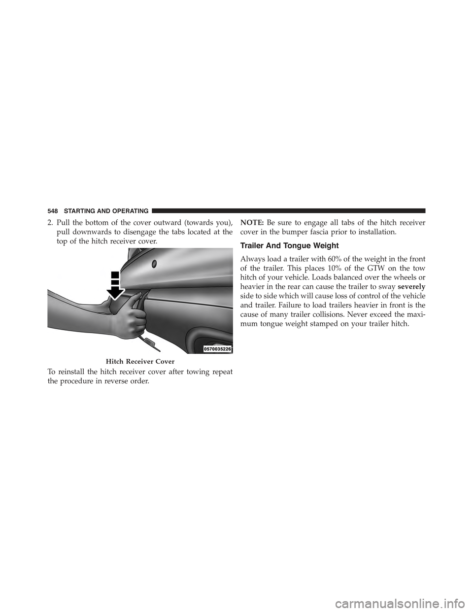
2. Pull the bottom of the cover outward (towards you),
pull downwards to disengage the tabs located at the
top of the hitch receiver cover.
To reinstall the hitch receiver cover after towing repeat
the procedure in reverse order.
NOTE:Be sure to engage all tabs of the hitch receiver
cover in the bumper fascia prior to installation.
Trailer And Tongue Weight
Always load a trailer with 60% of the weight in the front
of the trailer. This places 10% of the GTW on the tow
hitch of your vehicle. Loads balanced over the wheels or
heavier in the rear can cause the trailer to swayseverely
side to side which will cause loss of control of the vehicle
and trailer. Failure to load trailers heavier in front is the
cause of many trailer collisions. Never exceed the maxi-
mum tongue weight stamped on your trailer hitch.
Hitch Receiver Cover
548 STARTING AND OPERATING
Page 615 of 717
Engine Air Cleaner Filter Installation
NOTE:Inspect and clean the housing if dirt or debris is
present before replacing the air filter element.
1. Install the air cleaner filter element into the housing
assembly with the air cleaner filter inspection surface
facing downward.
2. Install the air cleaner cover onto the housing assembly
locating tabs.
3. Latch the spring clips and lock the air cleaner cover to
the housing assembly.
Accessory Drive Belt Inspection
WARNING!
•Do not attempt to inspect an accessory drive belt
with vehicle running.
•When working near the radiator cooling fan, dis-
connect the fan motor lead. The fan is temperature
controlled and can start at any time regardless of
ignition switch position. You could be injured by
the moving fan blades.
•You can be badly injured working on or around a
motor vehicle. Only do service work for which you
have the knowledge and the proper equipment. If
you have any doubt about your ability to perform a
service job, take your vehicle to a competent me-
chanic.
7
MAINTAINING YOUR VEHICLE 613
Page 623 of 717
6. Remove the A/C air filter by pulling it straight out of
the housing.
7. Install the A/C air filter with the arrow on the filter
pointing toward the floor. When installing the filter
cover, make sure the retaining tabs fully engage the
cover.
CAUTION!
The A/C air filter is identified with an arrow to
indicate airflow direction through the filter. Failure
to properly install the filter will result in the need to
replace it more often.
8. Reinstall the glove compartment door on the glove
compartment door hinge and reattach the glove com-
partment tension tether by inserting the tether clip in
the glove compartment and sliding the clip away from
the face of the glove compartment door.
9. Push the door to the near closed position to reengage
the glove compartment travel stops.
NOTE:Ensure the glove compartment door hinges and
glove compartment travel stops are fully engaged.
Body Lubrication
Locks and all body pivot points, including such items as
seat tracks, door hinge pivot points and rollers, liftgate,
tailgate, decklid, sliding doors and hood hinges, should
be lubricated periodically with a lithium based grease,
such as MOPAR® Spray White Lube to assure quiet, easy
operation and to protect against rust and wear. Prior to
the application of any lubricant, the parts concerned
should be wiped clean to remove dust and grit; after
lubricating excess oil and grease should be removed.
Particular attention should also be given to hood latching
components to ensure proper function. When performing
other underhood services, the hood latch, release mecha-
nism and safety catch should be cleaned and lubricated.
7
MAINTAINING YOUR VEHICLE 621
Page 642 of 717

WARNING!(Continued)
•To avoid contamination from foreign matter or
moisture, use only new brake fluid or fluid that has
been in a tightly closed container. Keep the master
cylinder reservoir cap secured at all times. Brake
fluid in a open container absorbs moisture from the
air resulting in a lower boiling point. This may
cause it to boil unexpectedly during hard or pro-
longed braking, resulting in sudden brake failure.
This could result in a collision.
•Overfilling the brake fluid reservoir can result in
spilling brake fluid on hot engine parts, causing
the brake fluid to catch fire. Brake fluid can also
damage painted and vinyl surfaces, care should be
taken to avoid its contact with these surfaces.
(Continued)
WARNING!(Continued)
•Do not allow petroleum based fluid to contaminate
the brake fluid. Brake seal components could be
damaged, causing partial or complete brake failure.
This could result in a collision.
Front/Rear Axle Fluid
For normal service, periodic fluid level checks are not
required. When the vehicle is serviced for other reasons
the exterior surfaces of the axle assembly should be
inspected. If gear oil leakage is suspected inspect the
fluid level. Refer to “Fluids, Lubricants, and Genuine
Parts” in “Maintaining Your Vehicle” for further informa-
tion.
Front Axle Fluid Level Check
The front axle oil level needs to be no lower than 1/8 in
(3 mm) below the bottom of the fill hole.
640 MAINTAINING YOUR VEHICLE
Page 666 of 717
CAUTION!
Do not touch the new bulb with your fingers. Oil
contamination will severely shorten bulb life. If the
bulb comes in contact with any oily surface, clean the
bulb with rubbing alcohol.
Front Fog Lamps
1. Reach through the cutout in the splash shield and
disconnect the wiring harness from the fog lamp
connector.
2. Firmly grasp the bulb by the two latches and squeeze
them together to unlock the bulb from the back of the
front fog lamp housing.
3. Pull the bulb straight out from the keyed opening in
the housing.
CAUTION!
•Do not touch the new bulb with your fingers. Oil
contamination will severely shorten bulb life. If
the bulb comes in contact with any oily surface,
clean the bulb with rubbing alcohol.
•Always use the correct bulb size and type for
replacement. An incorrect bulb size or type may
overheat and cause damage to the lamp, the socket
or the lamp wiring.
4. Align the index tabs of the front fog lamp bulb with
the slots in the collar of the bulb opening on the back
of the front fog lamp housing.
5. Insert the bulb into the housing until the index tabs are
engaged in the slots of the collar.
664 MAINTAINING YOUR VEHICLE