Page 313 of 717
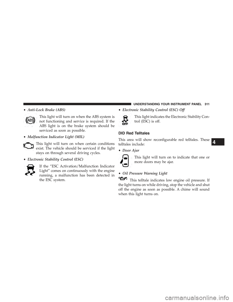
•Anti-Lock Brake (ABS)
This light will turn on when the ABS system is
not functioning and service is required. If the
ABS light is on the brake system should be
serviced as soon as possible.
•Malfunction Indicator Light (MIL)
This light will turn on when certain conditions
exist. The vehicle should be serviced if the light
stays on through several driving cycles.
•Electronic Stability Control (ESC)
If the “ESC Activation/Malfunction Indicator
Light” comes on continuously with the engine
running, a malfunction has been detected in
the ESC system.
•Electronic Stability Control (ESC) Off
This light indicates the Electronic Stability Con-
trol (ESC) is off.
DID Red Telltales
This area will show reconfigurable red telltales. These
telltales include:
•Door Ajar
This light will turn on to indicate that one or
more doors may be ajar.
•Oil Pressure Warning Light
This telltale indicates low engine oil pressure. If
the light turns on while driving, stop the vehicle and shut
off the engine as soon as possible. A chime will sound
when this light turns on.
4
UNDERSTANDING YOUR INSTRUMENT PANEL 311
Page 419 of 717
!BRAKE SYSTEM.......................472
!ELECTRONIC BRAKE CONTROL SYSTEM . . . .473
▫Anti-Lock Brake System (ABS)............473
▫Traction Control System (TCS)............475
▫Brake Assist System (BAS)...............475
▫Electronic Roll Mitigation (ERM)..........476
▫Electronic Stability Control (ESC)..........477
▫Trailer Sway Control (TSC)..............480
▫Hill Start Assist (HSA).................481
▫Ready Alert Braking — If Equipped........483
▫Rain Brake Support — If Equipped.........483
▫Hill Descent Control (HDC) — If Equipped
(Four-Wheel Drive Models With MP3023
Two-Speed Transfer Case Only)...........484
▫Selec Speed Control (SSC) — If Equipped
(Four-Wheel Drive Models With MP3023
Two-Speed Transfer Case Only)...........488
▫ESC Activation/Malfunction Indicator Light And
ESC OFF Indicator Light................491
!TIRE SAFETY INFORMATION.............493
▫Tire Markings........................493
▫Tire Identification Number (TIN)...........497
▫Tire Terminology And Definitions..........498
▫Tire Loading And Tire Pressure...........500
!TIRES — GENERAL INFORMATION........505
▫Tire Pressure........................505
▫Tire Inflation Pressures.................506
▫Tire Pressures For High Speed Operation . . . .508
5
STARTING AND OPERATING 417
Page 442 of 717
WARNING!
Do not downshift for additional engine braking on a
slippery surface. The drive wheels could lose their
grip and the vehicle could skid, causing a collision or
personal injury.
FOUR-WHEEL DRIVE OPERATION
Quadra-Trac I® Operating Instructions/
Precautions — If Equipped
The Quadra-Trac I® is a single-speed (HI range only)
transfer case, which provides convenient full-time four-
wheel drive. No driver interaction is required. The Brake
Traction Control (BTC) System, which combines standard
ABS and Traction Control, provides resistance to any
wheel that is slipping to allow additional torque transfer
to wheels with traction.
NOTE:The Quadra-Trac I® system is not appropriate
for conditions where 4WD LOW range is recommended.
Refer to “Off-Road Driving Tips” in “Starting and Oper-
ating” for further information.
Quadra-Trac II® Operating Instructions/
Precautions — If Equipped
The Quadra-Trac II® transfer case is fully automatic in
the normal driving 4WD AUTO mode. The Quadra-Trac
II® transfer case provides three mode positions:
•4WD HI
•NEUTRAL
•4WD LOW
This transfer case is fully automatic in the 4WD HI mode.
When additional traction is required, the 4WD LOW
position can be used to lock the front and rear driveshafts
together and force the front and rear wheels to rotate at
440 STARTING AND OPERATING
Page 460 of 717
NOTE:On Summit models the lower front fascia is not
removable.
Lower Front Fascia Removal:
1. Remove the seven quarter turn fasteners.
2. Starting on one side of the vehicle, disengage lower
fascia from the upper fascia. Grasp the portion inside
the wheel well. Pulling it downwards and toward you,
separate the tabs from the slots in the upper fascia.
3. Continue working your way across the vehicle, sepa-
rating the remaining tabs from the slots in the upper
fascia.
NOTE:Do not allow the lower fascia to freely hang from
the tabs in the opposite corner as damage to lower and
upper fascia may result.
4. Store the lower fascia in a safe location.
Front Air Dam
1—FrontBumper2 — Front Air Dam Fasteners
458 STARTING AND OPERATING
Page 462 of 717

NOTE:Only models with the Off Road Package are
equipped with the a protective connector.
5. Remove the plug from the protective connector and
install on the sensor.
6. Insert the wiring harness connector into the protective
connector.
7. Store sensor and bracket in a safe place.
NOTE:All cruise control functions will be disabled when
the radar sensor is disconnected.
Radar sensor installation procedure (If equipped with
Adaptive Cruise Control [ACC]):
1. Disconnect the wiring harness connector from the
protective connector on the bumper beam.
2. Remove plug from radar sensor and install in protec-
tive connector.
3. Using the previously scribed marks, reinstall the radar
sensor and bracket using the two fasteners.
NOTE:Some alignment may be required upon fascia
installation to align sensor with fascia.
4. Install the wiring harness connector into the radar
sensor.
NOTE:If you receive a fault, see your authorized dealer
they may need to perform a sensor alignment.
Lower Front Fascia Installation (This will only work if
you have a helper. We suggest):
1. Starting at the center of the vehicle, engage a sufficient
number of tabs to support the weight of the lower
fascia (typically one or two tabs) into the upper fascia.
2. Working your way outward, engage the tabs into the
slots on one side of the vehicle.
460 STARTING AND OPERATING
Page 463 of 717
3. Return to the center of the vehicle and repeat Step 2 to
the opposite side of the vehicle.
NOTE:
•It may be necessary to apply additional force to
individual tabs to make sure they are fully engaged.
•Do not use any tools to apply additional force to the
tabs as damage to the upper and lower fascias may
result.
4. Reinstall the seven quarter turn fasteners.
Quadra-Lift™ — If Equipped
When off-roading, it is recommended that the lowest
useable vehicle height that will clear the current obstacle
or terrain be selected. The vehicle height should then be
raised as required by the changes in terrain.
The Selec-Terrain™ switch will automatically change the
vehicle to the optimized height based on the Selec-
Terrain™ switch position. The vehicle height can be
changed from the default height for each Selec-Terrain™
mode by normal use of the air suspension switches. Refer
to “Quadra-Lift™ – If Equipped” in “Starting and Oper-
ating” for further information.
When To Use 4WD LOW Range — If Equipped
When off-road driving, shift to 4WD LOW for additional
traction. This range should be limited to extreme situa-
tions such as deep snow, mud, or sand where additional
low speed pulling power is needed. Vehicle speeds in
excess of 25 mph (40 km/h) should be avoided when in
4WD LOW range.
5
STARTING AND OPERATING 461
Page 475 of 717
In the event power assist is lost for any reason (i.e.,
repeated brake applications with the engine off) the
brakes will still function. However, the effort required to
brake the vehicle will be much greater than that required
with the power system operating.
ELECTRONIC BRAKE CONTROL SYSTEM
Your vehicle is equipped with an advanced electronic
brake control system that includes the Anti-Lock Brake
System (ABS), Traction Control System (TCS), Brake
Assist System (BAS), Electronic Roll Mitigation (ERM),
and Electronic Stability Control (ESC). All five of these
systems work together to enhance vehicle stability and
control in various driving conditions.
Also, your vehicle may be equipped with Trailer Sway
Control (TSC), Hill Start Assist (HSA), Ready Alert
Braking (RAB), Rain Brake Support (RBS) and, if it has
four-wheel drive with the MP 3023 two-speed transfer
case, Hill Descent Control (HDC), Selec Speed Control
(SSC).
Anti-Lock Brake System (ABS)
The Anti-Lock Brake System (ABS) is designed to aid the
driver in maintaining vehicle control under adverse
braking conditions. The system operates with a separate
computer to modulate hydraulic pressure to prevent
wheel lock-up and help avoid skidding on slippery
surfaces.
All vehicle wheels and tires must be the same size and
type, and tires must be properly inflated to produce
accurate signals for the computer.
5
STARTING AND OPERATING 473
Page 476 of 717
WARNING!
Significant over or under-inflation of tires, or mixing
sizes of tires or wheels on the vehicle can lead to loss
of braking effectiveness.
The Anti-Lock Brake System conducts a low speed self-
test at about 12 mph (20 km/h). If for any reason your
foot is on the brake when the vehicle reaches 12 mph
(20 km/h), this check will be delayed until 25 mph
(40 km/h).
The Anti-Lock Brake System pump motor runs during
the self-test, and during an ABS stop, to provide the
regulated hydraulic pressure. The motor pump makes a
low humming noise during operation; this is normal.
WARNING!
•Pumping of the Anti-Lock Brakes will diminish
their effectiveness and may lead to a collision.
Pumping makes the stopping distance longer. Just
press firmly on your brake pedal when you need to
slow down or stop.
•The Anti-Lock Brake System (ABS) cannot prevent
the natural laws of physics from acting on the
vehicle, nor can they increase braking or steering
efficiency beyond that afforded by the condition of
the vehicle brakes and tires or the traction afforded.
•The ABS cannot prevent collisions, including those
resulting from excessive speed in turns, following
another vehicle too closely, or hydroplaning.
•The capabilities of an ABS-equipped vehicle must
never be exploited in a reckless or dangerous
manner which could jeopardize the user’s safety or
the safety of others.
474 STARTING AND OPERATING