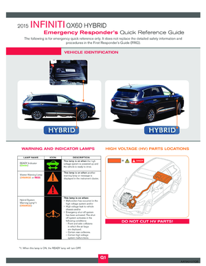
Page 17 of 42
: Up to 1,000V For protection from high voltage
electrical shock.
Insulated gloves
Insulated shoes
–")
3-1 Preparation Items
Preparation Items Specification Purpose
PPE (personal protective equipment): Up to 1,000V For protection from high voltage
electrical shock.
Insulated gloves
Insulated shoes
–
Safety shield
– To protect eyes when around high
voltage components and wiring.
Safety Glasses
Leather glovesMust be able to fasten tight
around the wrist. To protect insulated gloves.
Wrenches
Size:10mm To remove the 12-volt battery
terminal bolt.
Solvent resistant protection gloves
Solvent resistant protection shoes – To utilize in the event of a high
voltage battery electrolytic solutionleak.
Absorbent pad The same pad used for internal combustion engine fluids can beused.To absorb any high voltage battery
electrolytic solution leakage.
Standard fire fighting equipment
Standard fire fighting equipment.
Depending on type of fire
(vehicle or battery) use standard
fire fighting equipment (water or
extinguisher) . To extinguish a fire.
Insulated tape InsulatingTo cover any damaged harnesses
to protect from and prevent
electrical shock. Tape should
cover all bare or damaged wire.
3-1.1 Personal Protective Equipment (PPE) Protective Wear Control
Perform an inspection of the Personal Protective Equipment (PPE) items before beginning work. Do not use
any damaged PPE items.
FRG–17
Page 18 of 42

3-1.2 Daily Inspection
This inspection is performed before and after use. The responder who will be using the items should
perform the inspection and check for deterioration and damage.• Insulated rubber gloves should be inspected for scratches, holes and tears. (Visual check and airleakage test)
• Insulated safety boots should be inspected for holes, damage, nails, metal pieces, wear or other problems on the soles. (Visual check)
• Insulated rubber sheet should be inspected for tears. (Visual check)
3-1.3 Insulated Tools
When performing work at locations where high voltage is applied (such as terminals) , use insulated tools
meeting 1,000V/300A specifications.
3-2 Vehicle Immobilization and Stabilization
If possible, immobilize the vehicle by turning the 12-volt system OFF and stabilize it with a wheel chock(s) .
Stabilize the vehicle with cribbing, by removing air from the tires, or utilize the Lift Airbag Equipment for rescue.
•To avoid electrical shock, do not put the Lift Airbag Equipment for rescue and
wheel chock(s) under the high voltage components and harnesses.
=
AAYIA0265ZZ
FRG–18
Page 19 of 42
 system has
been designed to automatically shut off")
3-3 How to Handle a Damaged Vehicle at an Accident Scene
NOTE:
If any air bags have deployed in the following 3 situations, the high-voltage (HV) system has
been designed to automatically shut off at the time of deployment.
The Infiniti QX60 HYBRID high-voltage system incorporates capacitors which are energized whenever the
high-voltage system is on. If the high-voltage system is shut down (either through one of the built-in
automatic mechanisms or manually through one of the procedures explained in this FRG) , the capacitors
will begin to gradually discharge.Complete discharge requires approximately 10 minutes after
high-voltage system shut down. It is within this period of time that responders must be most cautious.
When arriving to an incident involving an Infiniti QX60 HYBRID, the vehicle should be approached with
caution and inspected for the level of damage. In addition to overall vehicle condition (location and
severity of body damage, air bag deployment, etc.) , the high-voltage system should be assessed
specifically. The locations of the high-voltage component parts are illustrated in this FRG. Refer to
2-2 High Voltage-Related and 12-Volt-Related Component Locations and Descriptions (FRG–11).
Appropriate personal protective equipment (PPE) must always be worn when approaching a vehicle of
unknown condition, as described in this FRG.
Situation 1) High voltage system intact, occupants can be accessed without extrication tools
The HV system can be shut down by following the procedure in this guide, while wearing appropriate PPE.
After HV system shut down, occupant assistance can begin immediately, and no wait period is necessary.
Situation 2) High voltage system intact, occupants cannot be accessed without extrication tools
The HV system can be shut down by following the procedure in this guide, while wearing appropriate PPE.
After HV system shut down, absolute care must be taken never to cut through or damage any HV system
wiring, battery or components within approximately ten (10) minutes of HV system shut down ,
but occupant assistance operations using extrication equipment can begin immediately. The locations of the
HV components are illustrated in this guide.
Situation 3) High-voltage (HV) system damaged
If there is any evidence that the HV system has been compromised (such as arcing/sparking, orange wiring
harnesses cut or damaged, HV component casings damaged, etc.) , the responder may still be at risk of
high voltage exposure. The vehicle must be approached with extreme caution prior to initiating any system
shut down procedures or rendering assistance to occupants. Appropriate PPE must always be worn as
described in this guide, and the approximate ten (10) minute wait time must be observed after
HV system shut down in order to ensure the system is de-energized.
In rare situations where vehicle damage is very severe, HV system shut down procedures as described in
this guide may not work. In these instances extreme caution and appropriate risk management must be
followed to prevent shock or electrocution to the responder or occupant.
FRG–19
Page 20 of 42

3-3.1 High Voltage System Shut-Down Procedure
Any of the following procedures can shut down the high voltage system. The first response operation should
only begin after shutting down the high voltage system. If the vehicle is heavily damaged, for example the
high voltage battery is deformed, broken or cracked, appropriate PPE must always be used and the high
voltage battery and high voltage components must not be touched. PPE must always be worn when
touching or working on high voltage components.
DANGER
•Failure to properly shut down the high voltage system before the Emergency
Response Procedures are performed will result in serious injury or death from
electrical shock. To prevent serious injury or death, NEVER touch high voltage
harnesses or components without always wearing appropriate Personal Protective
Equipment (PPE) . PPE must always be worn when touching or working on high
voltage components.
•
When contact with high voltage components or high voltage harnesses is
unavoidable, or when there is risk of such contact, you must always wear appropriate
PPE. PPE must always be worn when touching or working on high voltage components.
•The vehicle contains parts that contain powerful magnets. If a person who is wearing
a pacemaker or other medical device is close to these parts, the medical device may be
affected by the magnets. Such persons must not perform work on the vehicle.
• Be sure to verify that the READY
indicator is off (if possible) , and the high voltage
system is stopped.
• After the high voltage system is shut down, please wait approximately ten (10) minutes for complete discharge of the high voltage capacitor. While waiting, do not operate any
vehicle functions.
NOTE:
The high voltage full discharge takes approximately ten (10) minutes.
• After shutting down the high voltage system and removing the 12-volt battery negative (-) terminal, wait at least three (3) minutes to discharge the air bag capacitor. Even though
the 12-volt battery negative (-) is disconnected, the Supplemental Restraint System (SRS)
air bag maintains voltage at least three (3) minutes. During this time, there is a possibility
of sudden SRS air bag inflation due to harness short circuit or damage and it may cause
serious injuries.
• The 12V system will remain active even after the 12-volt battery negative (-) terminal is removed while the high voltage system is active.This is because the charging system
will not shut down and power will be supplied to the 12V system and high voltage systemcontinuously.
Before disconnecting the 12-volt battery terminal, if necessary, lower the windows, adjust the steering
column, adjust the seats, unlock the doors, open the liftgate, etc. as required. Once the 12-volt battery is
disconnected, power controls will not operate. FRG–20
Page 21 of 42

Powering Down the High Voltage System
The high voltage system can be shut down with any 1 of the following procedures:• Turn OFF the power switch and disconnect the 12-volt battery. Refer to
Primary Procedure
(FRG–21)
.
• Remove the underhood fuse for the high voltage control system and disconnect the 12-volt battery. Refer to
Alternate Procedure 1 (Remove Fuses) (FRG–23).
• Remove the service plug and disconnect the 12-volt battery. Refer to
Alternate Procedure 2
(Remove Service Plug) (FRG–25)
.
Primary Procedure
NOTE: Before disconnecting the 12-volt battery terminal, if necessary, lower the windows, adjust
the steering column, adjust the seats, unlock the doors, etc. Once 12-volt battery is
disconnected, power controls will not operate.
1. If possible, check the READY
indicator status in the instrument cluster. If it is on, the high
voltage system is active.
2. Place the shift selector in the Park (P) position.
3. Push the ignition switch once to turn OFF the high voltage system. Verify that the READY indicator is off
and then continue to the next steps to open the hood for
12-volt battery negative cable access.
If the READY indicator does not turn off, refer to
Alternate Procedure 1 (Remove Fuses) (FRG–23).
4. If possible, keep the Infiniti Intelligent Key at least 5 meters (16 feet) away from the vehicle.
AAYIA0191ZZ
ACC
LOCK
(OFF)
ON
AAYIA0271ZZ
AAYIA0340ZZ
FRG–21
Page 22 of 42
5. Pull release handle (1) and pull up release lever (2) to open hood.
6. Remove traction motor inverter cover (1) .
7. Disconnect negative (-) battery cable and cover it withinsulated tape.
8. Wait approximately ten (10) minutes for complete discharge of the high voltage capacitor
after the battery cable has been disconnected.
9. Perform the first response action.
1
2
AAYIA0272ZZ
1
AAYIA0273ZZ
AAYIA0274ZZ
FRG–22
Page 23 of 42
Alternate Procedure 1 (Remove Fuses)
NOTE:Before removing any fuses, if necessary, lower the windows, adjust the steering column,
adjust the seats, unlock the doors, etc. Once fuses are removed, power controls will notoperate. 1. Pull release handle (1) and pull up release lever (2) to open the hood.
2. Release clips (A) and remove fuse box cover (1) .
: Vehicle front
3. Remove IGCT RLY fuse (F/L V IGCT RLY 50A) .
4. If you cannot identify the correct fuse, remove all the fuses.
To avoid unintended reinstallation and risk of
electrical shock and severe personal injury or death, the
rescuer should carry the fuse or fuses on his/her person
and cover the fuse box with insulated tape.
1
2
AAYIA0272ZZ
1
A
AAYIA0303ZZ
F/L V IGCT RLY 50A (Red)
AAYIA0071GB
FRG–23
Page 24 of 42
5. Remove traction motor inverter cover (1) .
6. Disconnect negative (-) battery cable and cover it withinsulated tape.
7. Wait approximately ten (10) minutes for complete discharge of the high voltage capacitor
after the fuse panel and battery cable have been disconnected.
8. Perform the first response action.
1
AAYIA0273ZZ
AAYIA0274ZZ
FRG–24


 and pull up release lever (2) to open hood.
6. Remove traction motor inverter cover (1) .
7. Disconnect negative (-) battery cable and cover it withinsulated tape.
8. Wait")

NOTE:Before removing any fuses, if necessary, lower the windows, adjust the steering column,
adjust the seats, unlock the doors, etc. Once fuses are removed, pow")
 .
6. Disconnect negative (-) battery cable and cover it withinsulated tape.
7. Wait approximately ten (10) minutes for complete discharge of the high volta")