Page 9 of 43
 2. Hybrid System Overheated Stop Vehicle Warning (Vehicle Information Display)
3. Hybrid System Warning Lamp (Orange) 4")
1-3 Warning and Indicator Lamp Information1. Master Warning Lamp (Orange or Red) 2. Hybrid System Overheated Stop Vehicle Warning (Vehicle Information Display)
3. Hybrid System Warning Lamp (Orange) 4. READY Indicator (Green)
Lamp Name Icon Description
READY Indicator (Green)
This lamp is on when the high voltage system is powered up and
the vehicle is ready to drive.
Master Warning Lamp
(Orange or Red)
This lamp is on when another warning lamp or message is
displayed in the instrument cluster.
Hybrid System
Warning Lamp (Orange)
This lamp is on or blinking when:
• Malfunction has occurred in the hybrid control system and/or
• High voltage leak to vehicle chassis and/or
• Emergency shut-off system has been activated. The shut-off system activates in the following conditions:
– Front and side collisions in which the air bags are deployed.
– Certain rear collisions.
– Certain high voltage system malfunctions.
00 0
40
80
120
160
200
240
280
km/h
MPH
20
40
1 2
3
4 5
6
7
8
9
0
PWR
RPMx1000
6080
100
120
140
160
180
1
1/2
1234
Hybrid System Overheated Stop Vehicle
Warning
AAYIA0179ZZ
FRG–9
Page 10 of 43

2. Basic High Voltage System and 12-Volt System Information
2-1 Battery Information
The Q50 HYBRID utilizes two batteries in order to supply both high and low voltage.
2-1.1 12-Volt Battery• The Q50 HYBRID contains a conventional lead-acid12-volt battery.
• The 12-volt battery is located in the trunk, on the left side, concealed by a trim cover (A) .
• The 12-volt battery is charged by the high voltage battery through the DC/DC converter.
2-1.2 High Voltage Battery • The Q50 HYBRID contains a high voltage battery.
• The high voltage battery is mounted in the trunk areabehind the rear seat, enclosed in a metal case and
concealed by trim cover.
• The high voltage battery stores energy at approximately 346 - 400 volts DC.
• A vent hose is provided to exhaust gasses outside the vehicle if necessary.
• An air vent (A) is located on the rear left hand lower C-pillar trim for battery cooling.
The high voltage battery supplies power to the following: • High voltage harnesses
• DC/DC converter
• Traction motor inverter
• Traction motor
• Electric air conditioner compressor
A
AAYIA0180ZZ
AAYIA0183ZZ
A
AAYIA0184ZZ
FRG–10
Page 11 of 43
2-2 High Voltage-Related and 12-Volt-Related Component Locations and Descriptions
NOTE:Components with white number in black background are high voltage components.
No. Component Location Description� Traction Motor Inverter Engine compartment
(rear passenger side) Converts the DC power stored in the high
voltage battery to three-phase AC power and
controls motor torque (revolution) by regulating
the motor current. The inverter has a built in
high voltage capacitor.
� Traction Motor Built-into the trans-
mission Converts three-phase alternating current (AC)
power to drive power (torque) which propels
the vehicle.
5
1
34
6
7
2
AAYIA0181ZZ
FRG–11
Page 12 of 43
 The high voltage battery stores and outputs DC
power (Maximum voltage 400V) needed to
propel the vehicle.
DC")
No. Component Location Description� High voltage Battery
Trunk area (behind
rear seat back) The high voltage battery stores and outputs DC
power (Maximum voltage 400V) needed to
propel the vehicle.
DC/DCConverter Trunk area (mounted
to top of high voltagebattery) The DC/DC converter reduces the voltage of
the high voltage battery to provide power to the
12-volt battery in order to operate the vehicle’s
electric components (headlights, audio system,
etc.) .
� Service Plug Trunk area (below
parcel shelf; behind
access door in trimpanel) This is used to disable the high voltage system.
� 12-volt Battery Trunk area (left side
behind trim panel) A lead-acid battery that supplies power to the
low voltage devices.
� High VoltageHarnesses Trunk area (on high
voltage battery) ,
under floor pan,
engine compartment Orange-colored power cables carry high DC
voltage between each of the high voltagecomponents.
� Electric AirConditionerCompressor Engine compartment
(front driver side)
Air conditioner compressor
2-3 High Voltage Battery Pack Specifications
High Voltage Battery Specifications
High voltage battery voltage 346V (400V max.)
Number of high voltage battery modules in the pack 12 modules (96 cells)
High voltage battery module voltage 28.8V each
High voltage battery dimensions
29.63 x 17.81 x 14.85 in. (752.5 x 452.4 x 377.1 mm)
High voltage battery weight 108.05 lbs (49 kg)
FRG–12
Page 13 of 43
 and negative (-) circuits are insulatedfrom the metal chassis.
Reducing the risk of electrocution The high voltage com")
2-4 High Voltage Safety Measures
Circuit insulation The high voltage positive (+) and negative (-) circuits are insulatedfrom the metal chassis.
Reducing the risk of electrocution The high voltage components and harnesses have insulated cases or orange-colored coverings which provide insulation and easy identification.
The high voltage battery case is electrically connected to the vehicle ground.
This connection helps protect the vehicle occupants and emergency
responders from high voltage electrical shock.
Identification The high voltage components are labeled “WARNING” similar to label shown below. All high voltage harnesses are coated in orange.
2-4.1 Warning Labels
WARNING/AVERTISSEMENT
To avoid serious injury, keep clear engine parts at all times. Engine may start at any time if the start switch and the the READY lamps
on the instrument panel are "ON". Make sure both lamps are "OFF" before working in the engine compartment. See Owners Manual.
Pour éviter des blessures graves, assurez-vous que les témoins START SWITCH et READY dans le tableau d e bord sont éteints
(OFF) avant d'entreprendre tout travail à I'intérieur du compartiment moteur. Le moteur peut démarrer à tout moment si le contacteur
d'allumage est à la position ON et que les témoins READY du tableau de bord sont allumés. Assurez-vous que les deux
témoins sont éteints avant de travailler dans le compartiment moteur. Reportez-vous au manuel du conducteur.
B
W A R N I N G / A V E R T I S S E M E N T / A C H T U N G
Make sure READY lamp is "OFF" before working in the engine compartment.
Assurez-vous que les témoin READY est "OFF" avant d e travailler dans le compartiment du moteur.
Bitte gehen Sie sicher, dass die READY-Kontrolleuch te "AUS" ist, bevor Sie jegliche Arbeit
im Motorraum beginnen. D
AAYIA0419ZZ
AAYIA0010ZZ
FRG–13
Page 14 of 43

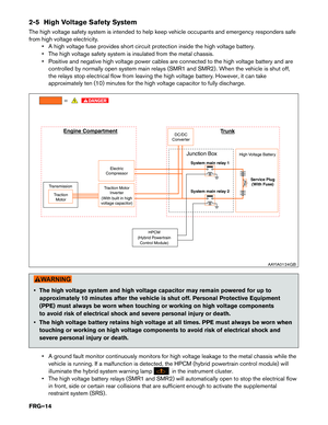
2-5 High Voltage Safety System
The high voltage safety system is intended to help keep vehicle occupants and emergency responders safe
from high voltage electricity.• A high voltage fuse provides short circuit protection inside the high voltage battery.
• The high voltage safety system is insulated from the metal chassis.
• Positive and negative high voltage power cables are connected to the high voltage battery and arecontrolled by normally open system main relays (SMR1 and SMR2) . When the vehicle is shut off,
the relays stop electrical flow from leaving the high voltage battery. However, it can take
approximately ten (10) minutes for the high voltage capacitor to fully discharge.
• The high voltage system and high voltage capacitor may remain powered for up to
approximately 10 minutes after the vehicle is shut off. Personal Protective Equipment
(PPE) must always be worn when touching or working on high voltage components
to avoid risk of electrical shock and severe personal injury or death.
• The high voltage battery retains high voltage at all times. PPE must always be worn when touching or working on high voltage components to avoid risk of electrical shock and
severe personal injury or death.
• A ground fault monitor continuously monitors for high voltage leakage to the metal chassis while the vehicle is running. If a malfunction is detected, the HPCM (hybrid powertrain control module) will
illuminate the hybrid system warning lamp
in the instrument cluster.
• The high voltage battery relays (SMR1 and SMR2) will automatically open to stop the electrical flow in front, side or certain rear collisions that are sufficient enough to activate the supplemental
restraint system (SRS) .
Trunk
Junction Box High Voltage Battery
System main relay 1
Service Plug (With Fuse)
System main relay 2
Transmission
Traction Motor Traction Motor
Inverter
(With built in high
voltage capacitor) Electric
Compressor DC/DC
Converter
Engine Compartment
HPCM
(Hybrid Powertrain Control Module)
AAYIA0124GB
FRG–14
Page 15 of 43

2-6 High Voltage Circuit Shut-Off System
This vehicle is equipped with a system to shut off the current from the high voltage battery by the following methods:
Service plug Positioned in the center area of the high voltage battery, this plug shuts offthe output of high voltage when manually removed.
System main relays
(located in the high
voltage battery) Controlled by the ignition switch, these relays are powered by the 12-volt
system and shut off high voltage from the high voltage battery.
Emergency shut-offsystem In the case of a collision (front and side collisions in which the air bags are
deployed, certain rear collisions) or certain system malfunctions this system
is designed to shut off the high voltage from the high voltage battery.
2-7 Preventing Electrical Shock 1. If it is necessary to touch any of the high voltage harnesses or components, always wearappropriate Personal Protective Equipment (PPE) (refer to
3-1 Preparation Items (FRG–17)) .
Shut off the high voltage system by referring to
3-3.1 High Voltage System Shut-Down
Procedure (FRG–20)
.
2. To avoid the risk of electrocution, NEVER touch the inside of the high voltage battery with bare hands after shutting off the high voltage system. The high voltage battery maintains charge even
though the high voltage system is shut down. PPE must always be worn when touching or
working on high voltage components.
3. Cover damaged high voltage components with insulated tape.
2-8 Emergency Medical Equipment
The high voltage system should not interfere with emergency medical equipment which must be used in or
near the vehicle at an accident scene.
FRG–15
Page 16 of 43

3. Emergency Response Steps
DANGER
•Failure to properly shut down the high voltage electrical system before the
Emergency Response Procedures are performed will result in serious injury or death
from electrical shock. To prevent serious injury or death, NEVER touch high voltage
harnesses or components without always wearing appropriate Personal Protective
Equipment (PPE) . PPE must always be worn when touching or working on high
voltage components.
•
If it is necessary to touch any of the high voltage harnesses or components you
must always wear appropriate PPE to avoid electrical shock. PPE must always beworn
when touching or working on high voltage components. Shut downthe high voltage
system by following the steps outlined in
3-3.1 High Voltage System Shut-Down
Procedure (FRG–20)
Wait approximately ten (10) minutes for complete discharge of
the high voltage capacitor after the high voltage system has been shut down.
• NEVER assume the Q50 HYBRID is shut OFF simply because it is quiet.
• If the READY
indicator is ON thehigh voltage system is active.
• If possible, besure to check the READY
indicator on the instrument cluster and
verify that theREADY
indicatoris OFF and the high voltage system is stopped.
FRG–16