Page 425 of 504
Maintenance
7-14
MAINTENANCE UNDER SEVERE USAGE CONDITIONS
The following items must be serviced more frequently on vehicles mainly used under severe driving conditions.
Refer to the chart below for the appropriate maintenance intervals.
R : Replace I : Inspect and if necessary, adjust, correct, clean or replace
Maintenance itemMaintenance
operationMaintenance intervalsDriving condition
Engine oil and
engine oil filterTheta 2.4 GDIRReplace every 7,500 km or 6 monthsA, B, C, D, E,
F, G, H, I, J, K, L
Theta 2.0 T-GDIRReplace every 5,000 km or 3 months
Air cleaner filterRReplace more frequently
depending on the conditionC, E
Spark plugs RReplace more frequently
depending on the conditionA, B, H, I
Steering gear rack, linkage and bootsIInspect more frequently
depending on the conditionC, D, E, F, G
Front suspension ball jointsIInspect more frequently
depending on the conditionC, D, E, F, G
Page 426 of 504

7-15
7
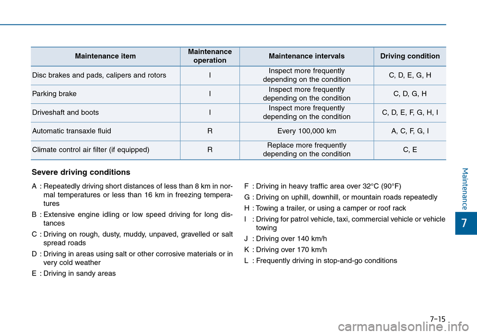
MaintenanceSevere driving conditions
A : Repeatedly driving short distances of less than 8 km in nor-
mal temperatures or less than 16 km in freezing tempera-
tures
B : Extensive engine idling or low speed driving for long dis-
tances
C : Driving on rough, dusty, muddy, unpaved, gravelled or salt
spread roads
D : Driving in areas using salt or other corrosive materials or in
very cold weather
E : Driving in sandy areasF : Driving in heavy traffic area over 32°C (90°F)
G : Driving on uphill, downhill, or mountain roads repeatedly
H : Towing a trailer, or using a camper or roof rack
I : Driving for patrol vehicle, taxi, commercial vehicle or vehicle
towing
J : Driving over 140 km/h
K : Driving over 170 km/h
L : Frequently driving in stop-and-go conditions
Maintenance itemMaintenance
operationMaintenance intervalsDriving condition
Disc brakes and pads, calipers and rotorsIInspect more frequently
depending on the conditionC, D, E, G, H
Parking brakeIInspect more frequently
depending on the conditionC, D, G, H
Driveshaft and bootsIInspect more frequently
depending on the conditionC, D, E, F, G, H, I
Automatic transaxle fluidREvery 100,000 kmA, C, F, G, I
Climate control air filter (if equipped)RReplace more frequently
depending on the conditionC, E
Page 430 of 504
7-19
7
Maintenance
Brake pads, calipers and
rotors
Check the pads for excessive wear,
discs for run out and wear, and
calipers for fluid leakage.
For more information on checking
the pads or lining wear limit, refer to
the HYUNDAI web site.
(http://brakeman
ual.hmc.co.kr)
Suspension mounting bolts
Check the suspension connections
for looseness or damage. Retighten
to the specified torque.
Steering gear box, linkage &
boots/lower arm ball joint
With the vehicle stopped and engine
off, check for excessive free-play in
the steering wheel.
Check the linkage for bends or dam-
age. Check the dust boots and ball
joints for deterioration, cracks, or
damage. Replace any damaged
parts.
Drive shafts and boots
Check the drive shafts, boots and
clamps for cracks, deterioration, or
damage. Replace any damaged
parts and, if necessary, repack the
grease.
Air conditioning refrigerant/
compressor
Check the air conditioning lines and
connections for leakage and dam-
age.
Page 467 of 504
7-56
Maintenance
Fuse NameSymbolFuse ratingCircuit Protected
SAFETY
WINDOW LH 25A Driver Safety Power Window Module
P/SEAT PASS 30A Passenger Seat Manual Switch
P/WDW LH 20A Power Window Main Switch, Rear Power Window Module LH
P/WDW RH 25A Power Window Main Switch, Rear Power Window Module RH Passenger Door Module,
Passenger Power Window Switch
DR LOCK 20A Door Lock Relay, Door Unlock Relay
S/HEATER FRT 25A Front Air Ventilation Seat Module, Front Seat Warmer Module
BRAKE SWITCH 10A Stop Lamp Switch, Immobiliser Module Smart Key Control Module
MODULE 8 7.5A BCM, Smart Key Control Module
SAFETY POWER
WINDOW RH 25A Passenger Safety Power Window Module
SMART KEY 15A Smart Key Control Module
BOOT 10A Boot Lid Relay, Fuel Filler Door & Boot Lid Switch
MODULE 7 10A Digital Clock, Driver/Passenger Door Module
Driver’s side fuse panel
Page 468 of 504

7-57
7
Maintenance
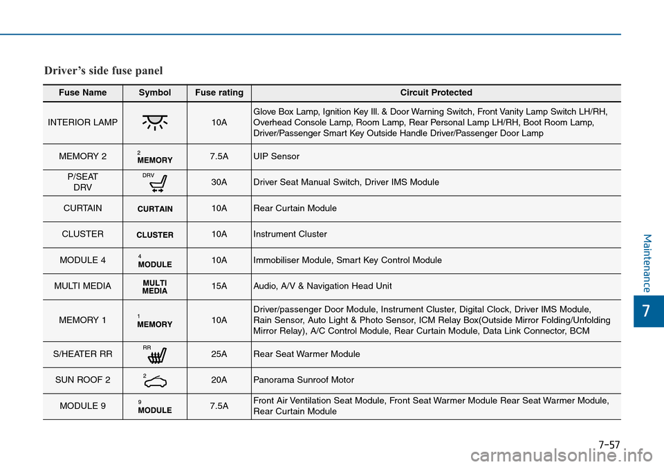
Fuse NameSymbolFuse ratingCircuit Protected
INTERIOR LAMP 10A Glove Box Lamp, Ignition Key Ill. & Door Warning Switch, Front Vanity Lamp Switch LH/RH,
Overhead Console Lamp, Room Lamp, Rear Personal Lamp LH/RH, Boot Room Lamp,
Driver/Passenger Smart Key Outside Handle Driver/Passenger Door Lamp
MEMORY 2 7.5A UIP Sensor
P/SEAT
DRV 30A Driver Seat Manual Switch, Driver IMS Module
CURTAIN 10A Rear Curtain Module
CLUSTER 10A Instrument Cluster
MODULE 4 10A Immobiliser Module, Smart Key Control Module
MULTI MEDIA 15A Audio, A/V & Navigation Head Unit
MEMORY 1 10A Driver/passenger Door Module, Instrument Cluster, Digital Clock, Driver IMS Module,
Rain Sensor, Auto Light & Photo Sensor, ICM Relay Box(Outside Mirror Folding/Unfolding
Mirror Relay), A/C Control Module, Rear Curtain Module, Data Link Connector, BCM
S/HEATER RR 25A Rear Seat Warmer Module
SUN ROOF 2 20A Panorama Sunroof Motor
MODULE 9 7.5A Front Air Ventilation Seat Module, Front Seat Warmer Module Rear Seat Warmer Module,
Rear Curtain Module
Driver’s side fuse panel
Page 470 of 504
7-59
7
Maintenance
Fuse NameSymbolFuse ratingCircuit Protected
5MODULE10A Front Console Switch, Blind Spot Detection Radar, Fuel Filler Door & Boot Lid Switch, Front
Parking Assist Sensor, Rear Parking Assist Sensor
IG1 25A PCB Block (Fuse - F1/F2/F7/F8)
Rear Fog Lamp 10A ICM Relay Box (Rear Fog Lamp Relay)
WASHER 15A Multifunction Switch (Wiper Low & Washer Switch)
POWER OUTLET 20A Cigarette Lighter
A/BAG 15A SRS Control Module
START 7.5A
[W/O Smart Key & IMMO.] ICM Relay Box (Burglar Alarm Relay)
[With Smart Key / IMMO.-A/T]
Transaxle Range Switch, PCM (G4KJ/G4KH)
[With Smart Key / IMMO.-M/T]
Ignition Lock & Clutch
Driver’s side fuse panel
Page 478 of 504
7-67
7
Maintenance
Rear combination light bulb
replacement
Type A
(1) Stop/Tail lamp
(2) Tail lamp
(3) Turn signal lamp
(4) Reverse lamp
Stop/Tail lamp and Turn signal lamp
1. Open the boot lid.
2. Remove the service cover by turn-
ing the lock anticlockwise and then
pulling it out.3. Remove the socket from the
assembly by turning the socket
anticlockwise until the tabs on the
socket align with the slots on the
assembly.
4. Remove the bulb from the socket
by pressing it in and rotating it
anticlockwise until the tabs on the
bulb align with the slots in the
socket. Pull the bulb out of the
socket.
5. Insert a new bulb by inserting it
into the socket and rotating it until
it locks into place.
OLF074063OLF074062
Stop/Tail lamp
Turn Signal lamp
OLF074060
Page 479 of 504
7-68
Maintenance
6. Install the socket in the assembly
by aligning the tabs on the socket
with the slots in the assembly.
Push the socket into the assembly
and turn the socket clockwise.
Reverse lamp and Tail lamp
1. Open the boot.
2. Loosen the retaining screw of the
boot lid cover and then remove the
cover.
3. Disconnect the connector and
then remove the socket by turning
the socket anticlockwise.4. Remove the bulb by pulling it
straight out.
5. Insert a new bulb by inserting it
into the socket and rotating it until
it locks into place.
6. Install the socket into the assembly
by aligning the tabs on the socket
with the slots in the assembly.
Push the socket into the assembly
and turn the socket clockwise.
7. Reinstall the boot lid cover by
pushing in the screw.
OLF074065OLF074064
Reverse lamp
Tail lamp