Page 727 of 785
Maintenance
52 7
Reset items
Items should be reset after the bat-
tery has been discharged or the bat-
tery has been disconnected.
• Auto up/down window
(See section 4)
• Sunroof (See section 4)
• Trip computer (See section 4)
• Climate control system
(See section 4)
• Clock (See section 4)
• Audio (See section 4)(Continued)
1. Turn off the battery charger
main switch.
2. Unhook the negative clamp
from the negative battery
terminal.
3. Unhook the positive clamp
from the positive battery
terminal.
• Before performing mainte-
nance or recharging the bat-
tery, turn off all accessories
and stop the engine.
• The negative battery cable
must be removed first and
installed last when the battery
is disconnected.WARNING- Recharging
battery
When recharging the battery,
observe the following precau-
tions:
• The battery must be removed
from the vehicle and placed in
an area with good ventilation.
• Do not allow cigarettes, sparks,
or flame near the battery.
• Watch the battery during
charging, and stop or reduce
the charging rate if the battery
cells begin gassing (boiling)
violently or if the temperature
of the electrolyte of any cell
exceeds 49°C (120°F).
• Wear eye protection when
checking the battery during
charging.
• Disconnect the battery charg-
er in the following order.
(Continued)
Page 743 of 785
Maintenance
68 7
FUSES
A vehicle’s electrical system is pro-
tected from electrical overload dam-
age by fuses.This vehicle has 2 fuse panels, one
located in the driver’s side panel bol-
ster, the other in the engine compart-
ment near the battery.
If any of your vehicle’s lights, acces-
sories, or controls do not work, check
the appropriate circuit fuse. If a fuse
has blown, the element inside the
fuse will be melted.
If the electrical system does not
work, first check the driver’s side
fuse panel.
Always replace a blown fuse with
one of the same rating.
Before replacing an open fuse, dis-
connect the negative battery cable.
If the replacement fuse blows, this
indicates an electrical problem. Avoid
using the system involved and imme-
diately consult an authorized
HYUNDAI dealer.
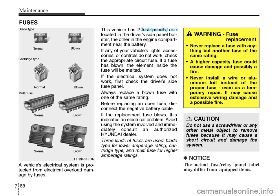
Three kinds of fuses are used: blade
type for lower amperage rating, car-
tridge type, and multi fuse for higher
amperage ratings.
✽NOTICE
The actual fuse/relay panel label
may differ from equipped items.
OLM079051N Normal Normal Blade type
Cartridge type
Multi fuseBlown
Blown
Normal Blown
Normal Blown
WARNING - Fuse
replacement
• Never replace a fuse with any-
thing but another fuse of the
same rating.
• A higher capacity fuse could
cause damage and possibly a
fire.
• Never install a wire or alu-
minum foil instead of the
proper fuse - even as a tem-
porary repair. It may cause
extensive wiring damage and
a possible fire.
CAUTION
Do not use a screwdriver or any
other metal object to remove
fuses because it may cause a
short circuit and damage the
system.
Page 744 of 785
769
Maintenance
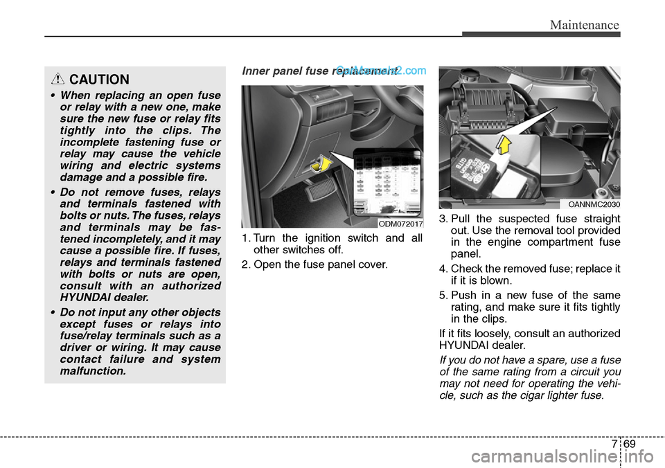
Inner panel fuse replacement
1. Turn the ignition switch and all
other switches off.
2. Open the fuse panel cover.3. Pull the suspected fuse straight
out. Use the removal tool provided
in the engine compartment fuse
panel.
4. Check the removed fuse; replace it
if it is blown.
5. Push in a new fuse of the same
rating, and make sure it fits tightly
in the clips.
If it fits loosely, consult an authorized
HYUNDAI dealer.
If you do not have a spare, use a fuse
of the same rating from a circuit you
may not need for operating the vehi-
cle, such as the cigar lighter fuse.
ODM072017
OANNMC2030
CAUTION
• When replacing an open fuse
or relay with a new one, make
sure the new fuse or relay fits
tightly into the clips. The
incomplete fastening fuse or
relay may cause the vehicle
wiring and electric systems
damage and a possible fire.
• Do not remove fuses, relays
and terminals fastened with
bolts or nuts. The fuses, relays
and terminals may be fas-
tened incompletely, and it may
cause a possible fire. If fuses,
relays and terminals fastened
with bolts or nuts are open,
consult with an authorized
HYUNDAI dealer.
• Do not input any other objects
except fuses or relays into
fuse/relay terminals such as a
driver or wiring. It may cause
contact failure and system
malfunction.
Page 745 of 785
Maintenance
70 7
If the headlights or other electrical
components do not work and the
fuses are OK, check the fuse block in
the engine compartment. If a fuse is
blown, it must be replaced.Fuse switch
Always, put the mode switch at the
ON position.
If you move the switch to the OFF
position, some items such as audio
and digital clock must be reset and
transmitter (or smart key) may not
work properly.
Engine compartment panel fuse
replacement
1. Turn the ignition switch and all
other switches off.
2. Remove the fuse box cover by
pressing the tab and pulling up.
ODM072019
CAUTION
Always place the fuse switch in
the ON position while driving
the vehicle.
OANNMC2032
Page 746 of 785
771
Maintenance
3. Check the removed fuse; replace it
if it is blown. To remove or insert
the fuse, use the fuse puller in the
engine compartment fuse panel.
4. Push in a new fuse of the same
rating, and make sure it fits tightly
in the clips. If it fits loosely, consult
an authorized HYUNDAI dealer.Multi fuse
If the multi fuse is blown, it must be
removed as follows:
1. Disconnect the negative battery
cable.
2. Remove the bolts shown in the
picture above.
3. Replace the fuse with a new one
of the same rating.
4. Reinstall in the reverse order of
removal.
✽NOTICE
If the multi fuse is blown, consult an
Authorized HYUNDAI Dealer.
OANNMC2033
CAUTION
After checking the fuse box in
the engine compartment,
securely install the fuse box
cover. If not, electrical failures
may occur from water leaking in.
Page 751 of 785
Maintenance
76 7
Engine compartment fuse panel
ODM072050
ODMNMC2015
Page 766 of 785
791
Maintenance
Waxing
Wax the vehicle when water will no
longer bead on the paint.
Always wash and dry the vehicle
before waxing. Use a good quality
liquid or paste wax, and follow the
manufacturer’s instructions. Wax all
metal trim to protect it and to main-
tain its luster.
Removing oil, tar, and similar materi-
als with a spot remover will usually
strip the wax from the finish. Be sure
to re-wax these areas even if the rest
of the vehicle does not yet need wax-
ing.CAUTION
• Wiping dust or dirt off the
body with a dry cloth will
scratch the finish.
• Do not use steel wool, abra-
sive cleaners, or strong deter-
gents containing highly alka-
line or caustic agents on
chrome-plated or anodized
aluminum parts. This may
result in damage to the pro-
tective coating and cause dis-
coloration or paint deteriora-
tion.
CAUTION
• Water washing in the engine
compartment including high
pressure water washing may
cause the failure of electrical
circuits located in the engine
compartment.
• Never allow water or other liq-
uids to come in contact with
electrical/electronic compo-
nents inside the vehicle as
this may damage them.
OJB037800
Page 772 of 785
797
Maintenance
EMISSION CONTROL SYSTEM
The emission control system of your
vehicle is covered by a written limited
warranty. Please see the warranty
information contained in the Service
Passport in your vehicle.
Your vehicle is equipped with an
emission control system to meet all
emission regulations.
There are three emission control
systems which are as follows.
(1) Crankcase emission control sys-
tem
(2) Evaporative emission control sys-
tem
(3) Exhaust emission control system
In order to assure the proper function
of the emission control systems, it is
recommended that you have your
car inspected and maintained by an
authorized HYUNDAI dealer in
accordance with the maintenance
schedule in this manual.Caution for the Inspection and
Maintenance Test (With Electronic
Stability Control (ESC) system)
• To prevent the vehicle from mis-
firing during dynamometer test-
ing, turn the Electronic Stability
Control (ESC) system off by
pressing the ESC switch.
• After dynamometer testing is
completed, turn the ESC system
back on by pressing the ESC
switch again.
1. Crankcase emission control
system
The positive crankcase ventilation
system is employed to prevent air
pollution caused by blow-by gases
being emitted from the crankcase.
This system supplies fresh filtered air
to the crankcase through the air
intake hose. Inside the crankcase,
the fresh air mixes with blow-by
gases, which then pass through the
PCV valve into the induction system.
2. Evaporative emission con-
trol (including ORVR:
Onboard Refueling Vapor
Recovery) system
The Evaporative Emission Control
System is designed to prevent fuel
vapors from escaping into the atmos-
phere.
(The ORVR system is designed to
allow the vapors from the fuel tank to
be loaded into a canister while refu-
eling at the gas station, preventing
the escape of fuel vapors into the
atmosphere.)
Canister
Fuel vapors generated inside the fuel
tank are absorbed and stored in the
onboard canister. When the engine is
running, the fuel vapors absorbed in
the canister are drawn into the surge
tank through the purge control sole-
noid valve.