Page 481 of 550
721
Maintenance
FUEL FILTER (FOR DIESEL)Draining water from fuel filterThe fuel filter for diesel engine plays an
important role of separating water from
fuel and accumulating the water in its
bottom.
If water accumulates in the fuel filter, the
warning light comes on when the ignition
switch is in the ON position.If this warning light illuminates,
we recommend that the sys-
tem by checked by a HYUNDAI
authorised repairer.
Extracting air from the fuel filterIf you drive until you have no fuel left or if
you replace the fuel filter, be sure to
extract air from the fuel system as it
makes it difficult to start the engine.
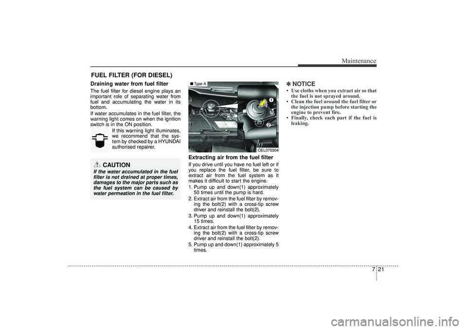
1. Pump up and down(1) approximately50 times until the pump is hard.
2. Extract air from the fuel filter by remov- ing the bolt(2) with a cross-tip screw
driver and reinstall the bolt(2).
3. Pump up and down(1) approximately 15 times.
4. Extract air from the fuel filter by remov- ing the bolt(2) with a cross-tip screw
driver and reinstall the bolt(2).
5. Pump up and down(1) approximately 5 times.
✽ ✽NOTICE• Use cloths when you extract air so that
the fuel is not sprayed around.
• Clean the fuel around the fuel filter or the injection pump before starting the
engine to prevent fire.
• Finally, check each part if the fuel is leaking.
CAUTION
If the water accumulated in the fuel
filter is not drained at proper times,damages to the major parts such as the fuel system can be caused bywater permeation in the fuel filter.
OEL070304
■ Type A
EL(FL) UK 7.QXP 3/4/2015 9:05 PM Page 21
Page 482 of 550
Maintenance22
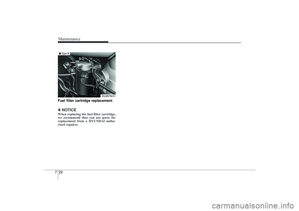
7Fuel filter cartridge replacement✽
✽
NOTICEWhen replacing the fuel filter cartridge,
we recommend that you use parts for
replacement from a HYUNDAI autho-
rised repairer.
OLM079011
■ Type B
EL(FL) UK 7.QXP 3/4/2015 9:05 PM Page 22
Page 493 of 550
733
Maintenance
TYRES AND WHEELS Tyre care
For proper maintenance, safety, and
maximum fuel economy, you must
always maintain recommended tyre
inflation pressures and stay within
the load limits and weight distribution
recommended for your vehicle.
Recommended cold tyre inflation
pressures
All tyre pressures (including the
spare) should be checked when the
tyres are cold. “Cold Tyres” means
the vehicle has not been driven for at
least three hours or driven less than
1 mile (1.6 km).
Recommended pressures must be
maintained for the best ride, top vehi-
cle handling, and minimum tyre
wear.
For recommended inflation pressure
refer to “Tyre and wheels” in section
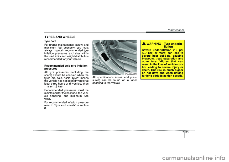
8.All specifications (sizes and pres-
sures) can be found on a label
attached to the vehicle.
WARNING - Tyre underin-
flation
Severe underinflation (10 psi
(0.7 bar) or more) can lead to
severe heat build-up, causing
blowouts, tread separation and
other tyre failures that can
result in the loss of vehicle con-
trol leading to severe injury or
death. This risk is much higher
on hot days and when driving
for long periods at high speeds.
OEL083008R
EL(FL) UK 7.QXP 3/4/2015 9:05 PM Page 33
Page 494 of 550
Maintenance34
7
WARNING - Tyre inflation
Overinflation or underinflation
can reduce tyre life, adversely
affect vehicle handling, and
lead to sudden tyre failure. This
could result in loss of vehicle
control and potential injury.
CAUTION - Tyre pressure
Always observe the following:
Check tyre pressure when the tyres are cold. (After vehiclehas been parked for at leastthree hours or hasn't beendriven more than 1 mile (1.6km) since startup.)
Check the pressure of your spare tyre each time youcheck the pressure of othertyres.
Never overload your vehicle. Be careful not to overload avehicle luggage rack if yourvehicle is equipped with one.
Worn, old tyres can cause accidents. If your tread isbadly worn, or if your tyreshave been damaged, replacethem.
CAUTION
Underinflation also results in excessive wear, poor handlingand reduced fuel economy.Wheel deformation also ispossible. Keep your tyre pres-sures at the proper levels. If atyre frequently needs refilling,we recommend that the sys-tem be checked by a HYUNDAIauthorised repairer.
Overinflation produces a harsh ride, excessive wear atthe centre of the tyre tread,and a greater possibility ofdamage from road hazards.
CAUTION
Warm tyres normally exceed recommended cold tyre pres-sures by 4 to 6 psi (0.28 to 0.41bar). Do not release air fromwarm tyres to adjust the pres-sure or the tyres will be under-inflated.
Be sure to reinstall the tyre inflation valve caps. Withoutthe valve cap, dirt or moisturecould get into the valve coreand cause air leakage. If avalve cap is missing, install anew one as soon as possible.
EL(FL) UK 7.QXP 3/4/2015 9:05 PM Page 34
Page 514 of 550
Maintenance54
7
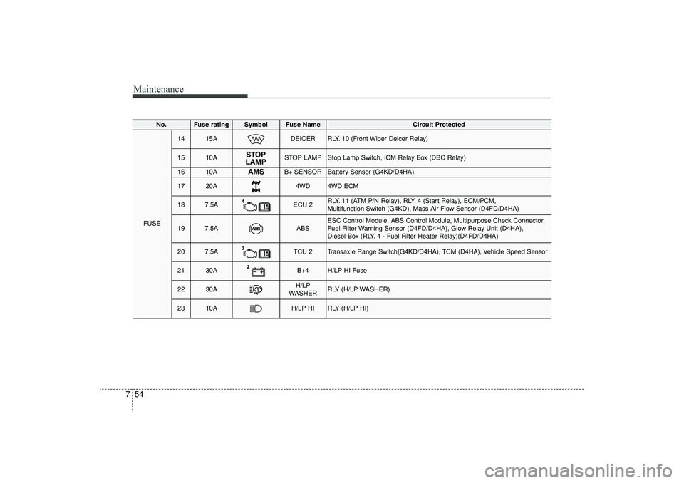
No.
Fuse rating
Symbol
Fuse Name
Circuit Protected
FUSE
14
15A
DEICER
RLY. 10 (Front Wiper Deicer Relay)
15
10A
STOP LAMP
Stop Lamp Switch, ICM Relay Box (DBC Relay)
16
10A
AMS
B+ SENSOR
Battery Sensor (G4KD/D4HA)
17
20A
4WD
4WD ECM
18
7.5A
ECU 2
RLY. 11 (ATM P/N Relay), RLY. 4 (Start Relay), ECM/PCM,
Multifunction Switch (G4KD), Mass Air Flow Sensor (D4FD/D4HA)
19
7.5A
ABS
ESC Control Module, ABS Control Module, Multipurpose Check Connector,
Fuel Filter Warning Sensor (D4FD/D4HA), Glow Relay Unit (D4HA),
Diesel Box (RLY. 4 - Fuel Filter Heater Relay)(D4FD/D4HA)
20
7.5A
TCU 2
Transaxle Range Switch(G4KD/D4HA), TCM (D4HA), Vehicle Speed Sensor
21
30A
B+4
H/LP HI Fuse
22
30A
H/LP
WASHER
RLY (H/LP WASHER)
23
10A
H/LP HI
RLY (H/LP HI)
EL(FL) UK 7.QXP 3/4/2015 9:07 PM Page 54
Page 515 of 550
755
Maintenance
Engine compartment sub fuse panel (Disel Engine)No.
Fuse rating
Fuse Symbol
Circuit Protected
Relay Symbol
Relay Type
1
50A
PTC Heater Relay #1
MICRO PLUG
2
50A
PTC Heater Relay #2
MICRO PLUG
3
50A
PTC Heater Relay #3
MICRO PLUG
4
30A
Fuel Filter Heater Relay
MICRO PLUG
5
80A
Glow Relay Unit
-
-
EL(FL) UK 7.QXP 3/4/2015 9:07 PM Page 55
Page 532 of 550
Maintenance72
7Bright-metal maintenance To remove road tar and insects, use a
tar remover, not a scraper or other
sharp object.
To protect the surfaces of bright-metal parts from corrosion, apply a coating of
wax or chrome preservative and rub to
a high luster.
During winter weather or in coastal areas, cover the bright metal parts with
a heavier coating of wax or preserva-
tive. If necessary, coat the parts with
non-corrosive petroleum jelly or other
protective compound.
Underbody maintenanceCorrosive materials used for ice and
snow removal and dust control may col-
lect on the underbody. If these materials
are not removed, accelerated rusting can
occur on underbody parts such as the
fuel lines, frame, floor pan and exhaust
system, even though they have been
treated with rust protection.
Thoroughly flush the vehicle underbody
and wheel openings with lukewarm or
cold water once a month, after off-road
driving and at the end of each winter. Pay
special attention to these areas because
it is difficult to see all the mud and dirt. It
will do more harm than good to wet down
the road grime without removing it. The
lower edges of doors, rocker panels, and
frame members have drain holes that
should not be allowed to clog with dirt;
trapped water in these areas can cause
rusting.
WARNING
After washing the vehicle, test the
brakes whilst driving slowly to see
if they have been affected by water.
If braking performance is impaired,
dry the brakes by applying them
lightly whilst maintaining a slow
forward speed.
EL(FL) UK 7.QXP 3/4/2015 9:08 PM Page 72
Page 536 of 550
Maintenance76
7EMISSION CONTROL SYSTEMThe emission control system of your
vehicle is covered by a written limited
warranty. Please see the warranty infor-
mation contained in the Service Passport
in your vehicle.
Your vehicle is equipped with an emis-
sion control system to meet all emission
regulations.
There are three emission control sys-
tems which are as follows.
(1) Crankcase emission control system
(2) Evaporative emission control system
(3) Exhaust emission control system
In order to assure the proper function of
the emission control systems, it is rec-
ommended that you have your car
inspected and maintained by a
HYUNDAI authorised repairer in accor-
dance with the maintenance schedule. Caution for the Inspection and
Maintenance Test (With Electronic
Stability Control (ESC) system)
To prevent the vehicle from misfir-
ing during dynamometer testing,
turn the Electronic Stability Control
(ESC) system off by pressing the
ESC switch.
After dynamometer testing is com- pleted, turn the ESC system back on
by pressing the ESC switch again.
1. Crankcase emission control systemThe positive crankcase ventilation sys-
tem is employed to prevent air pollution
caused by blow-by gases being emitted
from the crankcase. This system supplies
fresh filtered air to the crankcase through
the air intake hose. Inside the crankcase,
the fresh air mixes with blow-by gases,
which then pass through the PCV valve
into the induction system.
2. Evaporative emission controlSystemThe Evaporative Emission Control
System is designed to prevent fuel
vapours from escaping into the atmos-
phere.CanisterFuel vapours generated inside the fuel
tank are absorbed and stored in the
onboard canister. When the engine is
running, the fuel vapours absorbed in the
canister are drawn into the surge tank
through the purge control solenoid valve.Purge Control Solenoid Valve (PCSV)The purge control solenoid valve is con-
trolled by the Engine Control Module
(ECM); when the engine coolant temper-
ature is low during idling, the PCSV clos-
es so that evaporated fuel is not taken
into the engine. After the engine warms-
up during ordinary driving, the PCSV
opens to introduce evaporated fuel to the
engine.
EL(FL) UK 7.QXP 3/4/2015 9:08 PM Page 76