Page 121 of 498
441
Features of your vehicle
Inside rearview mirror
Before you start driving, adjust the
rearview mirror to the centre on the
view through the rear window.
Day/night rearview mirror
Make this adjustment before you
start driving and whilst the day/night
lever is in the day position.
Pull the day/night lever toward you to
reduce glare from the headlights of
the vehicles behind you during night
driving.
Remember that you lose some
rearview clarity in the night position.
MIRRORS
WARNING
Make sure your line of sight is not
obstructed. Do not place objects
in the rear seat, luggage compart-
ment, or behind the rear head-
rests which could interfere with
your vision through the rear win-
dow.
WARNING
To prevent serious injury during
an accident or deployment of
the air bag, do not modify the
rearview mirror and do not
install a wide mirror.
WARNING
NEVER adjust the mirror whilst
driving. This may cause loss of
vehicle control resulting in an
accident.
OMD040031
Day
Night
Page 122 of 498

Features of your vehicle
42 4
Electrochromic mirror (ECM)
(if equipped)
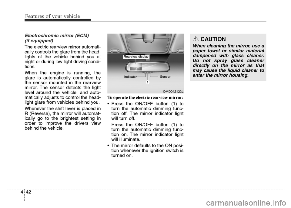
The electric rearview mirror automati-
cally controls the glare from the head-
lights of the vehicle behind you at
night or during low light driving condi-
tions.
When the engine is running, the
glare is automatically controlled by
the sensor mounted in the rearview
mirror. The sensor detects the light
level around the vehicle, and auto-
matically adjusts to control the head-
light glare from vehicles behind you.
Whenever the shift lever is placed in
R (Reverse), the mirror will automat-
ically go to the brightest setting in
order to improve the drivers view
behind the vehicle.To operate the electric rearview mirror:
• Press the ON/OFF button (1) to
turn the automatic dimming func-
tion off. The mirror indicator light
will turn off.
Press the ON/OFF button (1) to
turn the automatic dimming func-
tion on. The mirror indicator light
will illuminate.
• The mirror defaults to the ON posi-
tion whenever the ignition switch is
turned on.
OMD042122L IndicatorSensor
Rearview display
CAUTION
When cleaning the mirror, use a
paper towel or similar material
dampened with glass cleaner.
Do not spray glass cleaner
directly on the mirror as that
may cause the liquid cleaner to
enter the mirror housing.
Page 124 of 498
Features of your vehicle
44 4
Electric type (if equipped)
Adjusting the rearview mirrors:
Move the lever (1) either to the L
(Left) or R (Right) to select the
rearview mirror you would like to
adjust.
Use the mirror adjustment control to
position the selected mirror up,
down, left or right.
After adjustment, move the lever (1)
to the middle to prevent inadvertent
adjustment.
Folding the outside rearview mirror
Manual type
To fold the outside rearview mirror,
grasp the housing of the mirror and
then fold it toward the rear of the
vehicle.
OMD041035R
CAUTION
• The mirrors stop moving when
they reach the maximum
adjusting angles, but the
motor continues to operate
whilst the switch is pressed.
Do not press the switch longer
than necessary, the motor
may be damaged.
• Do not attempt to adjust the
outside rearview mirror by
hand or the motor may be
damaged.
OMD040036N/H
Page 129 of 498
449
Features of your vehicle
Engine Coolant Temperature
Gauge
This gauge shows the temperature
of the engine coolant when the igni-
tion switch is in the ON position.
Fuel Gauge
This gauge indicates the approxi-
mate amount of fuel remaining in the
fuel tank.
OMD044048K
OMD044048
■Type A
■Type BWARNING
Never remove the radiator cap
when the engine is hot. The
engine coolant is under pres-
sure and could cause severe
burns. Wait until the engine is
cool before adding coolant to
the reservoir.
CAUTION
If the gauge pointer moves
beyond the normal range area
toward the “H” position, it indi-
cates overheating that may
damage the engine.
Do not continue driving with an
overheated engine. If your vehi-
cle overheats, refer to “If the
Engine Overheats” in chapter 6.
OMD044049K
OMD044050
■Type A
■Type B
Page 147 of 498

467
Features of your vehicle
Parking Brake & Brake
Fluid Warning Light
This warning light illuminates:
• Once you set the ignition switch or
Engine Start/Stop button to the ON
position.
- It illuminates for approximately 3
seconds
- It remains on if the parking brake
is applied.
• When the parking brake is applied.
• When the brake fluid level in the
reservoir is low.
- If the warning light illuminates
with the parking brake released, it
indicates the brake fluid level is
low.If the brake fluid level in the reservoir
is low:
1. Drive carefully to the nearest safe
location and stop your vehicle.
2. With the engine stopped, check
the brake fluid level immediately
and add fluid as required (For
more details, refer to “Brake Fluid”
in chapter 7). Then check all brake
components for fluid leaks. If any
leak on the brake system is still
found, the warning light remains
on, or the brakes do not operate
properly, do not drive the vehicle.
In this case, we recommend that
you have the vehicle towed to an
authorised HYUNDAI dealer and
inspected.Dual-diagonal braking system
Your vehicle is equipped with a dual
diagonal braking system. This means
you still have braking on two wheels
even if one of the braking systems
should fail.
With only one of the braking systems
working, more than normal pedal
travel and greater pedal pressure are
required to stop the vehicle.
Also, the vehicle will not stop in as
short a distance with only a portion
of the brake system working.
If the brakes fail whilst you are driv-
ing, shift to a lower gear for addition-
al engine braking and stop the vehi-
cle as soon as it is safe to do so.
Page 160 of 498
Features of your vehicle
80 4
To flash the high beam headlights,
pull the lever towards you, then
release the lever. The high beams
will remain ON as long as you hold
the lever towards you.
Turn signals and lane change
signals
To signal a turn, move the lever down
for a right turn or up for a left turn to
position (A). The lever will return to
the OFF position when the turn is
completed.
To signal a lane change, move the
turn signal lever slightly and hold it in
position (B). The lever will return to
the OFF position when released.
WARNING
Do not use high beam when there
are other vehicles approaching
you. Using high beam could
obstruct the other driver's vision.
OMD041214R
OMD041215R
Page 169 of 498

489
Features of your vehicle
Windscreen washers
(if equipped)
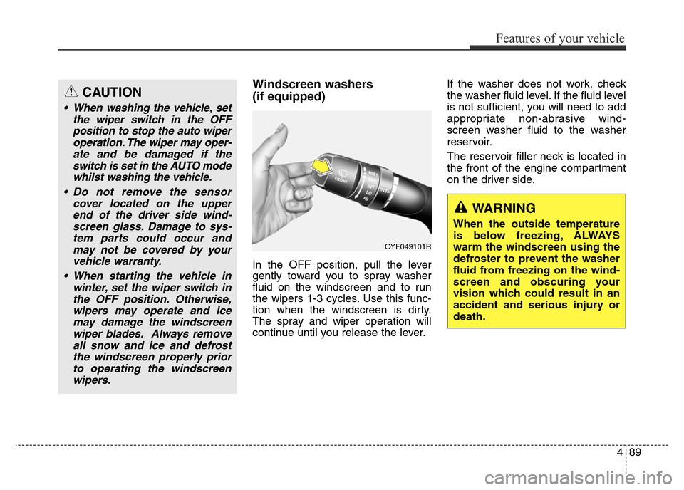
In the OFF position, pull the lever
gently toward you to spray washer
fluid on the windscreen and to run
the wipers 1-3 cycles. Use this func-
tion when the windscreen is dirty.
The spray and wiper operation will
continue until you release the lever.If the washer does not work, check
the washer fluid level. If the fluid level
is not sufficient, you will need to add
appropriate non-abrasive wind-
screen washer fluid to the washer
reservoir.
The reservoir filler neck is located in
the front of the engine compartment
on the driver side.
CAUTION
• When washing the vehicle, set
the wiper switch in the OFF
position to stop the auto wiper
operation. The wiper may oper-
ate and be damaged if the
switch is set in the AUTO mode
whilst washing the vehicle.
• Do not remove the sensor
cover located on the upper
end of the driver side wind-
screen glass. Damage to sys-
tem parts could occur and
may not be covered by your
vehicle warranty.
• When starting the vehicle in
winter, set the wiper switch in
the OFF position. Otherwise,
wipers may operate and ice
may damage the windscreen
wiper blades. Always remove
all snow and ice and defrost
the windscreen properly prior
to operating the windscreen
wipers.
OYF049101R
WARNING
When the outside temperature
is below freezing, ALWAYS
warm the windscreen using the
defroster to prevent the washer
fluid from freezing on the wind-
screen and obscuring your
vision which could result in an
accident and serious injury or
death.
Page 175 of 498

495
Features of your vehicle
Mode selection
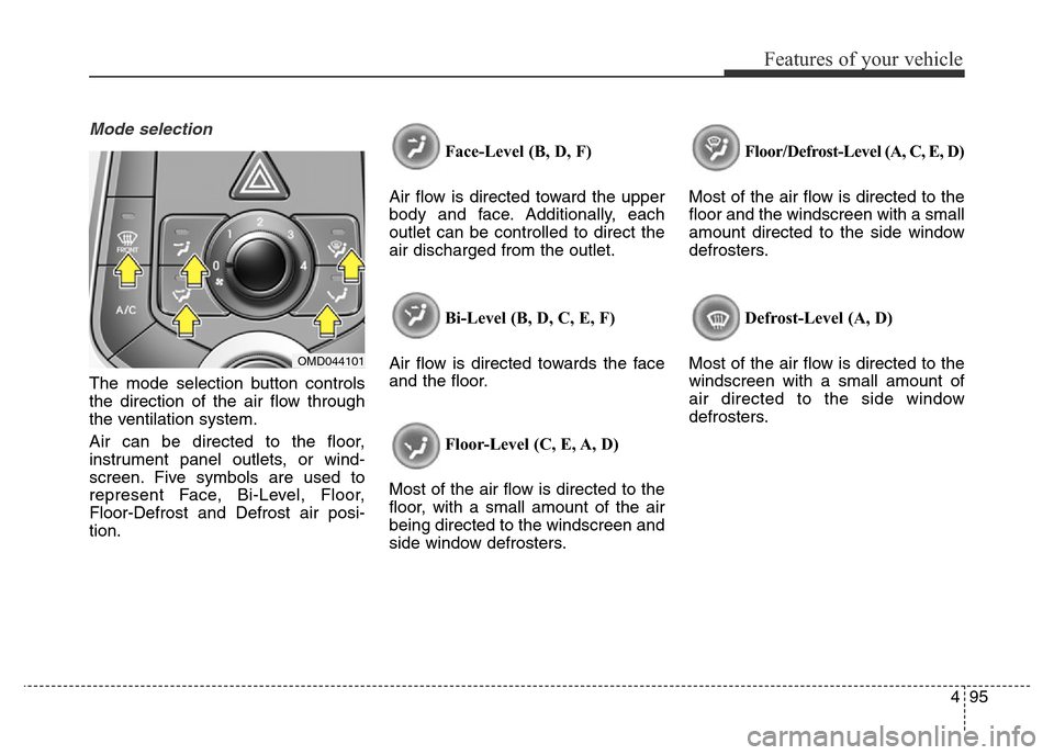
The mode selection button controls
the direction of the air flow through
the ventilation system.
Air can be directed to the floor,
instrument panel outlets, or wind-
screen. Five symbols are used to
represent Face, Bi-Level, Floor,
Floor-Defrost and Defrost air posi-
tion.Face-Level (B, D, F)
Air flow is directed toward the upper
body and face. Additionally, each
outlet can be controlled to direct the
air discharged from the outlet.
Bi-Level (B, D, C, E, F)
Air flow is directed towards the face
and the floor.
Floor-Level (C, E, A, D)
Most of the air flow is directed to the
floor, with a small amount of the air
being directed to the windscreen and
side window defrosters.Floor/Defrost-Level (A, C, E, D)
Most of the air flow is directed to the
floor and the windscreen with a small
amount directed to the side window
defrosters.
Defrost-Level (A, D)
Most of the air flow is directed to the
windscreen with a small amount of
air directed to the side window
defrosters.
OMD044101