2015 FORD SUPER DUTY set clock
[x] Cancel search: set clockPage 31 of 470
PRINCIPLE OF OPERATION
WARNINGS
Always drive and ride with your seatback upright and the lap belt snugand low across the hips.
To reduce the risk of injury, makesure children sit where they can beproperly restrained.
Never let a passenger hold a child onhis or her lap while the vehicle ismoving. The passenger cannotprotect the child from injury in a crashwhich may result in serious injury or death.
All occupants of the vehicle,including the driver, should alwaysproperly wear their safety belts, evenwhen an airbag supplemental restraintsystem is provided. Failure to properly wearyour safety belt could seriously increasethe risk of injury or death.
It is extremely dangerous to ride in acargo area, inside or outside of avehicle. In a crash, people riding inthese areas are more likely to be seriouslyinjured or killed. Do not allow people to ridein any area of your vehicle that is notequipped with seats and safety belts. Besure everyone in your vehicle is in a seatand using a safety belt properly.
In a rollover crash, an unbeltedperson is significantly more likely todie than a person wearing a safetybelt.
Each seating position in your vehiclehas a specific safety belt assemblywhich is made up of one buckle andone tongue that are designed to be usedas a pair. 1) Use the shoulder belt on theoutside shoulder only. Never wear theshoulder belt under the arm. 2) Neverswing the safety belt around your neck overthe inside shoulder. 3) Never use a singlebelt for more than one person.
WARNINGS
When possible, all children 12 yearsold and under should be properlyrestrained in a rear seating position.Failure to follow this could seriouslyincrease the risk of injury or death.
Safety belts and seats can becomehot in a vehicle that has been closedup in sunny weather; they could burna small child. Check seat covers andbuckles before you place a child anywherenear them.
Front and rear seat occupants,including pregnant women, shouldwear safety belts for optimumprotection in an accident.
All seating positions in this vehicle havelap and shoulder safety belts. Alloccupants of the vehicle should alwaysproperly wear their safety belts, even whenan airbag supplemental restraint systemis provided.
The safety belt system consists of:
•Lap and shoulder safety belts.
•Shoulder safety belt with automaticlocking mode, (except driver safetybelt).
•Height adjuster at the front outboardseating positions.
•Safety belt pretensioner at the frontoutboard seating positions.
•Safety belt warning light and chime.
•Crash sensors and monitoring systemwith readiness indicator.
28Super Duty (), enUSASafety Belts
Page 68 of 470
LIGHTING CONTROL
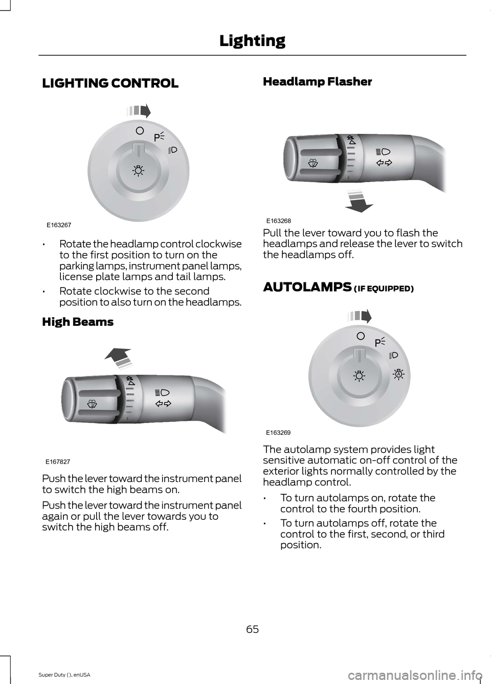
•Rotate the headlamp control clockwiseto the first position to turn on theparking lamps, instrument panel lamps,license plate lamps and tail lamps.
•Rotate clockwise to the secondposition to also turn on the headlamps.
High Beams
Push the lever toward the instrument panelto switch the high beams on.
Push the lever toward the instrument panelagain or pull the lever towards you toswitch the high beams off.
Headlamp Flasher
Pull the lever toward you to flash theheadlamps and release the lever to switchthe headlamps off.
AUTOLAMPS (IF EQUIPPED)
The autolamp system provides lightsensitive automatic on-off control of theexterior lights normally controlled by theheadlamp control.
•To turn autolamps on, rotate thecontrol to the fourth position.
•To turn autolamps off, rotate thecontrol to the first, second, or thirdposition.
65Super Duty (), enUSALightingE163267 E167827 E163268 E163269A
Page 142 of 470
WARNINGS
Keep sparks, flames and smokingmaterials away from fuel.
Stay outside your vehicle and do notleave the fuel pump unattendedwhen refueling your vehicle. This isagainst the law in some places.
Keep children away from the fuelpump; never let children pump fuel.
Do not use personal electronicdevices while refueling.
Use the following guidelines to avoidelectrostatic charge build-up when fillingan ungrounded fuel container:
•Place approved fuel container on theground.
•Do not fill a fuel container while it is inthe vehicle (including the cargo area).
•Keep the fuel pump nozzle in contactwith the fuel container while filling.
•Do not use a device that would holdthe fuel pump handle in the fill position.
Fuel Filler Cap
WARNINGS
The fuel system may be underpressure. If you hear a hissing soundnear the fuel filler door, do not refueluntil the sound stops. Otherwise, fuel mayspray out, which could cause seriouspersonal injury.
If you do not use the proper fuel fillercap, excessive pressure or vacuumin the fuel tank may damage the fuelsystem or cause the fuel cap to disengagein a collision, which may result in possiblepersonal injury.
Note:If you must replace the fuel filler cap,replace it with a fuel filler cap that isdesigned for your vehicle. The customerwarranty may be void for any damage to thefuel tank or fuel system if the correctgenuine Ford, Motorcraft® or other certifiedfuel filler cap is not used.
Your fuel tank filler cap has an indexeddesign with a 1/4th turn on and off feature.When fueling your vehicle:
1.Put the vehicle in P (Park).
2.Turn the engine off.
3.Carefully turn the filler capcounterclockwise until it spins off.
4.Pull to remove the cap from the fuelfiller pipe.
5.To install the cap, align the tabs on thecap with the notches on the filler pipe.
6.Turn the filler cap clockwise 1/4 of aturn clockwise until it clicks at leastonce.
If the Check Fuel Cap light or a Check FuelCap message appears in the instrumentcluster and stays on after you start theengine, the fuel filler cap may not beproperly installed.
If the fuel cap light remains on, at the nextopportunity, safely pull off of the road,remove the fuel filler cap, align the capproperly and reinstall it. The check fuel caplight or Check fuel cap message may notreset immediately; it may take severaldriving cycles for the indicators to turn off.A driving cycle consists of an enginestart-up (after four or more hours with theengine off) followed by normal city andhighway driving.
139Super Duty (), enUSAFuel and Refueling
Page 154 of 470
USING FOUR-WHEEL DRIVE
WARNING
For important information regardingsafe operation of this type of vehicle,See General Information (page263).
Note:Do not use 4X4 mode on dry, hardsurfaced roads. Doing so will produceexcessive noise, increase tire wear and maydamage drive components. 4X4 mode isonly intended for consistently slippery orloose surfaces.
Note:If 4X4 low is selected while thevehicle is moving above 3 mph (5 km/h),the 4WD system will not perform a shift.This is normal and should be no reason forconcern. Refer to Shifting to/from 4L (4X4Low) for proper operation.
Manual Shift On Stop (MSOS)4WD system (If Equipped)
Note:Some vehicles may be equipped withwheel ornaments that cover the 4x4 manualhub lock. These ornaments must beremoved to access the manual hub locks.
Note:The vehicle should not be driven in4X4 High or 4X4 Low modes with the hublocks set to FREE as this condition maydamage driveline system components.
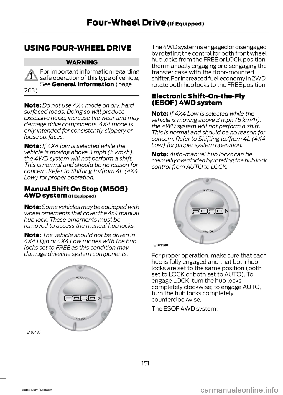
The 4WD system is engaged or disengagedby rotating the control for both front wheelhub locks from the FREE or LOCK position,then manually engaging or disengaging thetransfer case with the floor-mountedshifter. For increased fuel economy in 2WD,rotate both hub locks to the FREE position.
Electronic Shift-On-the-Fly(ESOF) 4WD system
Note:If 4X4 Low is selected while thevehicle is moving above 3 mph (5 km/h),the 4WD system will not perform a shift.This is normal and should be no reason forconcern. Refer to Shifting to/from 4L (4X4Low) for proper system operation.
Note:Auto-manual hub locks can bemanually overridden by rotating the hub lockcontrol from AUTO to LOCK.
For proper operation, make sure that eachhub is fully engaged and that both hublocks are set to the same position (bothset to LOCK or both set to AUTO). Toengage LOCK, turn the hub lockscompletely clockwise; to engage AUTO,turn the hub locks completelycounterclockwise.
The ESOF 4WD system:
151Super Duty (), enUSAFour-Wheel Drive (If Equipped)LOCKEERFE163187 LOCKOTUAE163188
Page 248 of 470
Note:Electrical or electronic accessoriesor components added to the vehicle by thedealer or the owner may adversely affectbattery performance and durability.
Your vehicle is equipped with a Motorcraftmaintenance-free battery which normallydoes not require additional water duringits life of service.
For longer, trouble-free operation, keep thetop of the battery clean and dry. Also,make certain the battery cables are alwaystightly fastened to the battery terminals.
If you see any corrosion on the battery orterminals, remove the cables from theterminals and clean with a wire brush. Youcan neutralize the acid with a solution ofbaking soda and water.
It is recommended that the negativebattery cable terminal be disconnectedfrom the battery if you plan to store yourvehicle for an extended period of time.
Because your vehicle’s engine iselectronically controlled by a computer,some control conditions are maintainedby power from the battery. When thebattery is disconnected or a new batteryis installed, the engine must relearn its idleand fuel trim strategy for optimumdriveability and performance. Flexible fuelvehicles (FFV) must also relearn theethanol content of the fuel for optimumdriveability and performance. To begin thisprocess
1.With the vehicle at a complete stop,set the parking brake.
2.Put the gearshift in P, turn off allaccessories.
3.Start the engine. Run the engine untilit reaches normal operatingtemperature.
4.Allow the engine to idle for at least oneminute.
5.Turn the A/C on and allow the engineto idle for at least one minute.
6.Release the parking brake. With yourfoot on the brake pedal and with theA/C on, put the vehicle in D and allowthe engine to idle for at least oneminute.
•If you do not allow the engine torelearn its idle trim, the idle qualityof your vehicle may be adverselyaffected until the idle trim iseventually relearned.
7.Drive the vehicle to complete therelearning process
•The vehicle may need to be driven10 mi (16 km) or more to relearn theidle and fuel trim strategy alongwith the ethanol content for flexiblefuel vehicles.
•For flexible fuel vehicles, if you areoperating on E85, you mayexperience poor starts or aninability to start the engine anddriveability problems until the fueltrim and ethanol content have beenrelearned.
If the battery has been disconnected or anew battery has been installed, the clockand radio settings must be reset once thebattery is reconnected.
Always dispose of automotivebatteries in a responsible manner.Follow your local authorized standardsfor disposal. Call your local authorizedrecycling center to find out more aboutrecycling automotive batteries.
Battery Management System (IfEquipped)
The battery management system (BMS)monitors battery conditions and takesactions to extend battery life. If excessivebattery drain is detected, the system maytemporarily disable certain electricalfeatures to protect the battery. Thoseelectrical accessories affected include therear defrost, heated/cooled seats, climate
245Super Duty (), enUSAMaintenance
Page 290 of 470
•To reduce the chances of interferencefrom another vehicle, perform thesystem reset procedure at least threefeet (one meter) away from anotherFord Motor Company vehicleundergoing the system reset procedureat the same time.
•Do not wait more than two minutesbetween resetting each tire sensor orthe system will time-out and the entireprocedure will have to be repeated onall four wheels.
•A double horn will sound indicating theneed to repeat the procedure.
Performing the System Reset Procedure
Read the entire procedure beforeattempting.
1.Drive the vehicle above 20 mph (32km/h) for at least two minutes, thenpark in a safe location where you caneasily get to all four tires and haveaccess to an air pump.
2.Place the ignition in the off position andkeep the key in the ignition.
3.Cycle the ignition to the on positionwith the engine off.
4.Turn the hazard flashers on then offthree times. You must accomplish thiswithin 10 seconds. If the reset modehas been entered successfully, the hornwill sound once, the system indicatorwill flash and a message is shown inthe information display. If this does notoccur, please try again starting at Step2. If after repeated attempts to enterthe reset mode, the horn does notsound, the system indicator does notflash and no message is shown in theinformation display, seek service fromyour authorized dealer.
5.Train the tire pressure monitoringsystem sensors in the tires using thefollowing system reset sequencestarting with the left front tire in thefollowing clockwise order: Left front(driver's side front tire), Right front(passenger's side front tire), Right rear(passenger's side rear tire), Left rear(driver's side rear tire)
6.Remove the valve cap from the valvestem on the left front tire. Decrease theair pressure until the horn sounds.Note: The single horn chirp confirmsthat the sensor identification code hasbeen learned by the module for thisposition. If a double horn is heard, thereset procedure was unsuccessful, andyou must repeat it.
7.Remove the valve cap from the valvestem on the right front tire. Decreasethe air pressure until the horn sounds.
8.Remove the valve cap from the valvestem on the right rear tire. Decrease theair pressure until the horn sounds.
9.Remove the valve cap from the valvestem on the left rear tire. Decrease theair pressure until the horn sounds.Training is complete after the hornsounds for the last tire trained (driver'sside rear tire), the system indicatorstops flashing, and a message is shownin the information display.
10.Turn the ignition off. If two short hornbeeps are heard, the reset procedurewas unsuccessful and you mustrepeat it. If after repeating theprocedure and two short beeps areheard when the ignition is turned tooff, seek assistance from yourauthorized dealer.
287Super Duty (), enUSAWheels and Tires
Page 294 of 470
1.Attach the spare tire lock key (A) to thejack handle (B).
2.Fully insert the jack handle (with oneextension) through the bumper holeand into the guide tube. The key andlock will engage with a slight push andcounterclockwise turn. You will feelsome resistance when you turn the jackhandle assembly.
3.Turn the handle counterclockwise andlower the spare tire until you can slidethe tire rearward and the cable is slack.
4.Remove the retainer through the centerof the wheel. If your vehicle is equippedwith a tether, perform the followingsteps.
5.Lift the spare tire on end to access thetether attachment.
6.Use the lug wrench to remove the lugnut from the spare tire tether.
7.If not replacing the spare or flat tire tothe underbody storage area, raise thewheel retainer up into the installedposition.
8.Use the attached fastener strap (onthe spare tire tether) to attach thetether end to the winch retainer priorto raising to the installed position.
Tire Change Procedure
WARNINGS
When one of the front wheels is offthe ground, the transmission alonewill not prevent the vehicle frommoving or slipping off the jack, even if thetransmission is in park (P).
To help prevent the vehicle frommoving when you change a tire, besure to place the transmission in park(P), set the parking brake and block (inboth directions) the wheel that isdiagonally opposite (other side and end ofthe vehicle) to the tire being changed.
Never get underneath a vehicle thatis supported only by a jack. If thevehicle slips off the jack, you orsomeone else could be seriously injured.
291Super Duty (), enUSAWheels and TiresE162798ABAB E162799 E162800
Page 295 of 470
WARNINGS
Do not attempt to change a tire onthe side of the vehicle close tomoving traffic. Pull far enough off theroad to avoid the danger of being hit whenoperating the jack or changing the wheel.
Always use the jack provided asoriginal equipment with your vehicle.If using a jack other than the oneprovided as original equipment with yourvehicle, make sure the jack capacity isadequate for the vehicle weight, includingany vehicle cargo or modifications.
Note:Passengers should not remain in thevehicle when the vehicle is being jacked.
Park on a level surface, set the parkingbrake and activate the hazard flashers.
1.Turn the engine off and block the wheelthat is diagonally opposite of the flattire using the wheel chock.Note: Lockthe manual hub on the wheel if thevehicle is a 4x4.
2.Remove the jack, jack handle, lugwrench and spare tire from thestowage locations.
3.Use the tip of the lug wrench to removeany wheel trim.
4.Loosen each wheel lug nut ½ turncounterclockwise, but do not removethem until the wheel is raised off theground.
F-250 and F-350 Single Rear WheelVehicles
1.Insert the hooked end of the jackhandle into the jack and use the handleto slide the jack under the vehicle.
2.Position the jack according to thefollowing guides:
Front (4x2)
Front driver side (4x4)
292Super Duty (), enUSAWheels and TiresE142551 E162801 E162802 E162803