2015 FORD SUPER DUTY sensor
[x] Cancel search: sensorPage 103 of 470
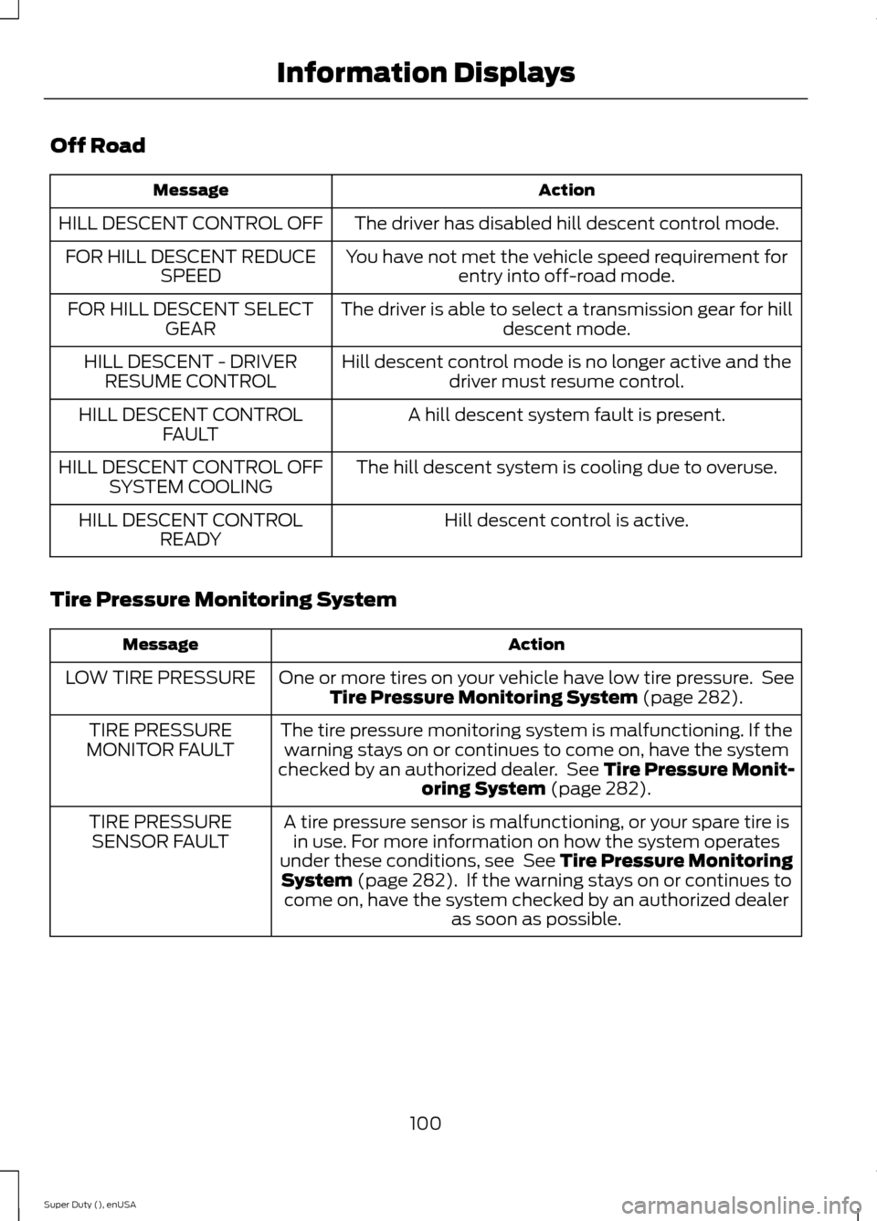
Off Road
ActionMessage
The driver has disabled hill descent control mode.HILL DESCENT CONTROL OFF
You have not met the vehicle speed requirement forentry into off-road mode.FOR HILL DESCENT REDUCESPEED
The driver is able to select a transmission gear for hilldescent mode.FOR HILL DESCENT SELECTGEAR
Hill descent control mode is no longer active and thedriver must resume control.HILL DESCENT - DRIVERRESUME CONTROL
A hill descent system fault is present.HILL DESCENT CONTROLFAULT
The hill descent system is cooling due to overuse.HILL DESCENT CONTROL OFFSYSTEM COOLING
Hill descent control is active.HILL DESCENT CONTROLREADY
Tire Pressure Monitoring System
ActionMessage
One or more tires on your vehicle have low tire pressure. SeeTire Pressure Monitoring System (page 282).LOW TIRE PRESSURE
The tire pressure monitoring system is malfunctioning. If thewarning stays on or continues to come on, have the systemchecked by an authorized dealer. See Tire Pressure Monit-oring System (page 282).
TIRE PRESSUREMONITOR FAULT
A tire pressure sensor is malfunctioning, or your spare tire isin use. For more information on how the system operatesunder these conditions, see See Tire Pressure MonitoringSystem (page 282). If the warning stays on or continues tocome on, have the system checked by an authorized dealeras soon as possible.
TIRE PRESSURESENSOR FAULT
100Super Duty (), enUSAInformation Displays
Page 133 of 470
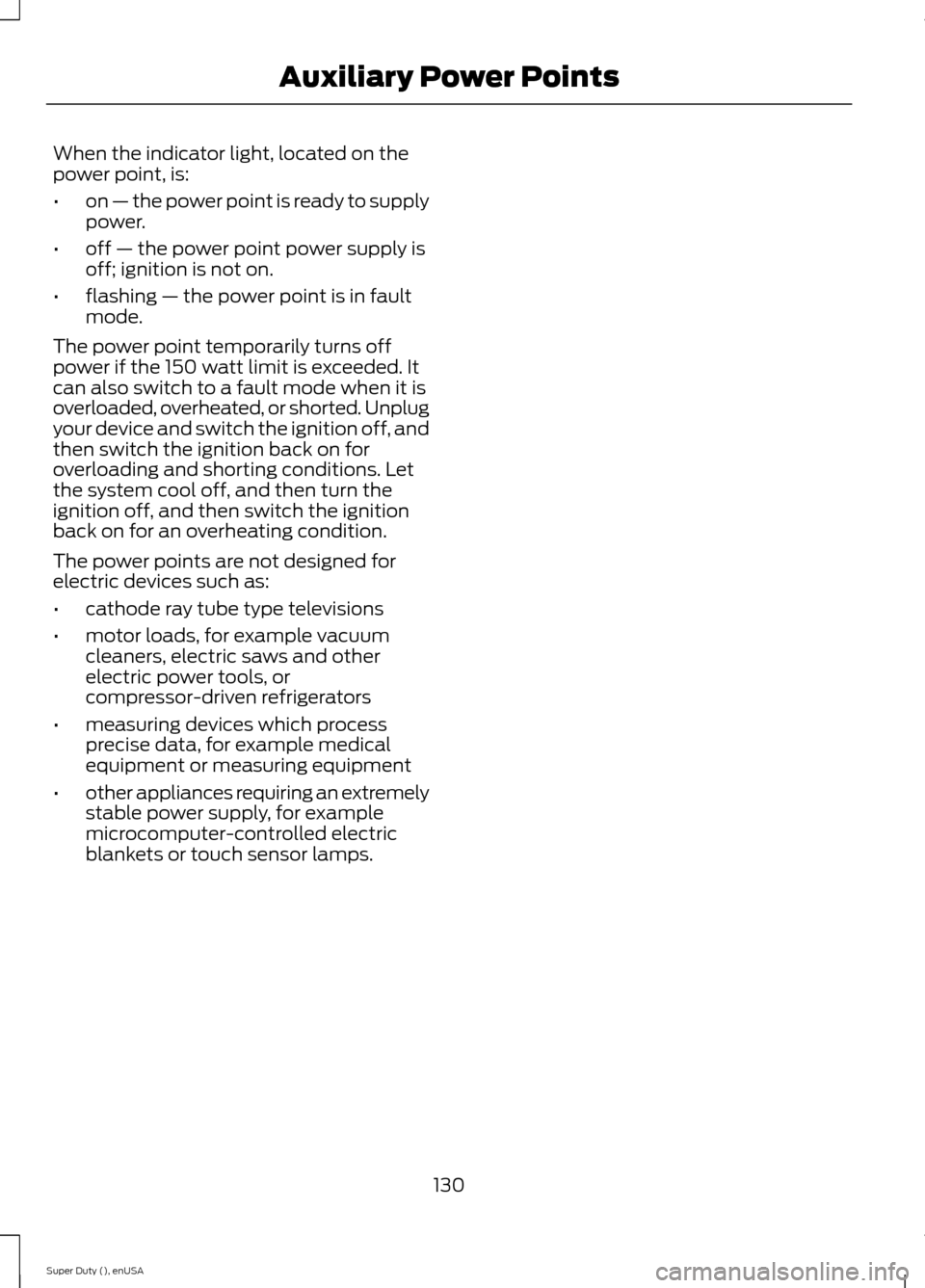
When the indicator light, located on thepower point, is:
•on — the power point is ready to supplypower.
•off — the power point power supply isoff; ignition is not on.
•flashing — the power point is in faultmode.
The power point temporarily turns offpower if the 150 watt limit is exceeded. Itcan also switch to a fault mode when it isoverloaded, overheated, or shorted. Unplugyour device and switch the ignition off, andthen switch the ignition back on foroverloading and shorting conditions. Letthe system cool off, and then turn theignition off, and then switch the ignitionback on for an overheating condition.
The power points are not designed forelectric devices such as:
•cathode ray tube type televisions
•motor loads, for example vacuumcleaners, electric saws and otherelectric power tools, orcompressor-driven refrigerators
•measuring devices which processprecise data, for example medicalequipment or measuring equipment
•other appliances requiring an extremelystable power supply, for examplemicrocomputer-controlled electricblankets or touch sensor lamps.
130Super Duty (), enUSAAuxiliary Power Points
Page 166 of 470
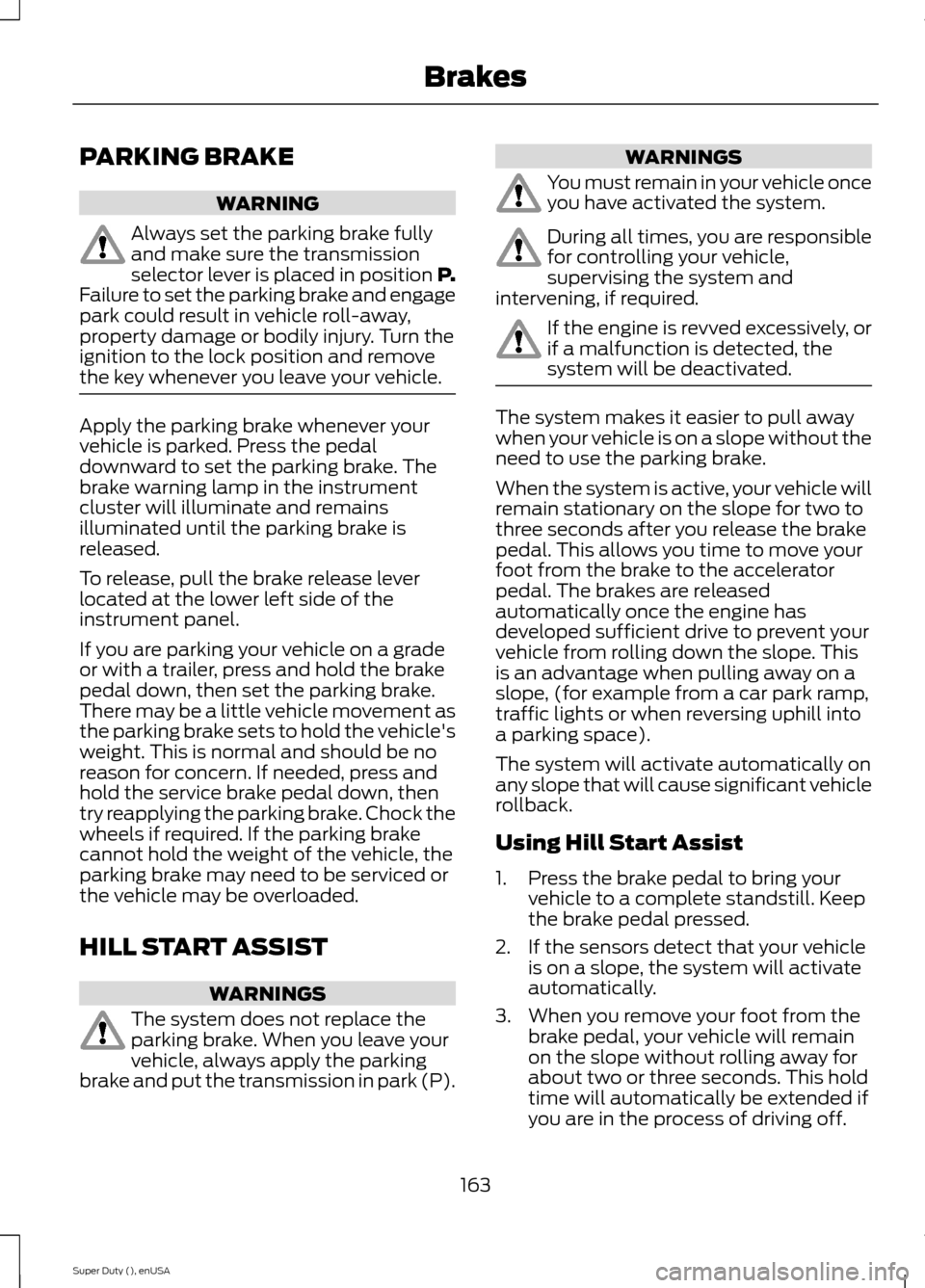
PARKING BRAKE
WARNING
Always set the parking brake fullyand make sure the transmissionselector lever is placed in position P.Failure to set the parking brake and engagepark could result in vehicle roll-away,property damage or bodily injury. Turn theignition to the lock position and removethe key whenever you leave your vehicle.
Apply the parking brake whenever yourvehicle is parked. Press the pedaldownward to set the parking brake. Thebrake warning lamp in the instrumentcluster will illuminate and remainsilluminated until the parking brake isreleased.
To release, pull the brake release leverlocated at the lower left side of theinstrument panel.
If you are parking your vehicle on a gradeor with a trailer, press and hold the brakepedal down, then set the parking brake.There may be a little vehicle movement asthe parking brake sets to hold the vehicle'sweight. This is normal and should be noreason for concern. If needed, press andhold the service brake pedal down, thentry reapplying the parking brake. Chock thewheels if required. If the parking brakecannot hold the weight of the vehicle, theparking brake may need to be serviced orthe vehicle may be overloaded.
HILL START ASSIST
WARNINGS
The system does not replace theparking brake. When you leave yourvehicle, always apply the parkingbrake and put the transmission in park (P).
WARNINGS
You must remain in your vehicle onceyou have activated the system.
During all times, you are responsiblefor controlling your vehicle,supervising the system andintervening, if required.
If the engine is revved excessively, orif a malfunction is detected, thesystem will be deactivated.
The system makes it easier to pull awaywhen your vehicle is on a slope without theneed to use the parking brake.
When the system is active, your vehicle willremain stationary on the slope for two tothree seconds after you release the brakepedal. This allows you time to move yourfoot from the brake to the acceleratorpedal. The brakes are releasedautomatically once the engine hasdeveloped sufficient drive to prevent yourvehicle from rolling down the slope. Thisis an advantage when pulling away on aslope, (for example from a car park ramp,traffic lights or when reversing uphill intoa parking space).
The system will activate automatically onany slope that will cause significant vehiclerollback.
Using Hill Start Assist
1.Press the brake pedal to bring yourvehicle to a complete standstill. Keepthe brake pedal pressed.
2.If the sensors detect that your vehicleis on a slope, the system will activateautomatically.
3.When you remove your foot from thebrake pedal, your vehicle will remainon the slope without rolling away forabout two or three seconds. This holdtime will automatically be extended ifyou are in the process of driving off.
163Super Duty (), enUSABrakes
Page 170 of 470
PRINCIPLE OF OPERATION
WARNINGS
Vehicle modifications involvingbraking system, aftermarket roofracks, suspension, steering system,tire construction and wheel and tire sizemay change the handling characteristicsof your vehicle and may adversely affectthe performance of the AdvanceTracsystem. In addition, installing any stereoloudspeakers may interfere with andadversely affect the AdvanceTrac system.Install any aftermarket stereo loudspeakeras far as possible from the front centerconsole, the tunnel, and the front seats inorder to minimize the risk of interfering withthe AdvanceTrac sensors. Reducing theeffectiveness of the AdvanceTrac systemcould lead to an increased risk of loss ofvehicle control, vehicle rollover, personalinjury and death.
Remember that even advancedtechnology cannot defy the laws ofphysics. It’s always possible to losecontrol of a vehicle due to inappropriatedriver input for the conditions. Aggressivedriving on any road condition can causeyou to lose control of your vehicleincreasing the risk of personal injury orproperty damage. Activation of theAdvanceTrac system is an indication thatat least some of the tires have exceededtheir ability to grip the road; this couldreduce the operator’s ability to control thevehicle potentially resulting in a loss ofvehicle control, vehicle rollover, personalinjury and death. If your AdvanceTracsystem activates, SLOW DOWN.
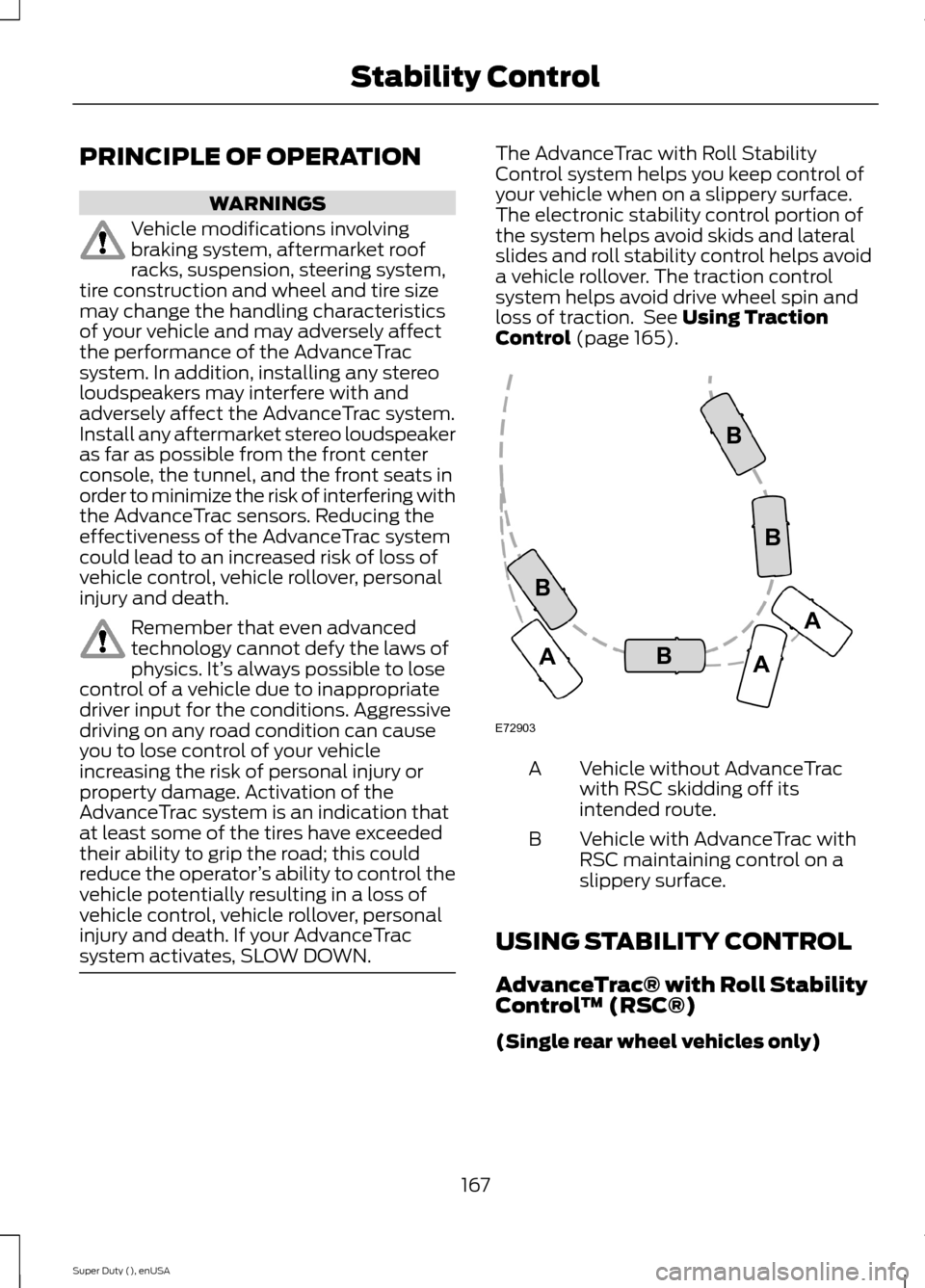
The AdvanceTrac with Roll StabilityControl system helps you keep control ofyour vehicle when on a slippery surface.The electronic stability control portion ofthe system helps avoid skids and lateralslides and roll stability control helps avoida vehicle rollover. The traction controlsystem helps avoid drive wheel spin andloss of traction. See Using TractionControl (page 165).
Vehicle without AdvanceTracwith RSC skidding off itsintended route.
A
Vehicle with AdvanceTrac withRSC maintaining control on aslippery surface.
B
USING STABILITY CONTROL
AdvanceTrac® with Roll StabilityControl™ (RSC®)
(Single rear wheel vehicles only)
167Super Duty (), enUSAStability ControlE72903AAABBBB
Page 175 of 470
PARKING AID (IF EQUIPPED)
WARNINGS
To help avoid personal injury, pleaseread and understand the limitationsof the system as contained in thissection. Sensing is only an aid for some(generally large and fixed) objects whenmoving in reverse on a flat surface atparking speeds. Traffic control systems,inclement weather, air brakes, and externalmotors and fans may also affect thefunction of the sensing system; this mayinclude reduced performance or a falseactivation.
To help avoid personal injury, alwaysuse caution when in R (Reverse) andwhen using the sensing system.
This system is not designed toprevent contact with small or movingobjects. The system is designed toprovide a warning to assist the driver indetecting large stationary objects to avoiddamaging the vehicle. The system may notdetect smaller objects, particularly thoseclose to the ground.
Certain add-on devices such as largetrailer hitches, bike or surfboard racksand any device that may block thenormal detection zone of the system, maycreate false beeps.
Note:Keep the sensors, located on thebumper or fascia, free from snow, ice andlarge accumulations of dirt. If the sensorsare covered, the system’s accuracy can beaffected. Do not clean the sensors withsharp objects.
Note:If your vehicle sustains damage tothe bumper or fascia, leaving it misalignedor bent, the sensing zone may be alteredcausing inaccurate measurement ofobstacles or false alarms.
Note:If your vehicle is equipped withMyKey™, it is possible to prevent turningthe sensing system off. See MyKey™ (page50).
Note:If your vehicle is equipped with a fullyintegrated electronic trailer brake controller(TBC) and a trailer with electric trailerbrakes is connected to your vehicle, the RSSwill be disabled. When the vehicle is shiftedinto reverse, the information display willremain in the Rear Park Aid Off selection.For more information on the TBC, SeeTrailer Sway Control (page 190).
The sensing system warns the driver ofobstacles within a certain range of thebumper area. The system turns onautomatically whenever the ignition isswitched on.
When receiving a detection warning, theradio volume is reduced to apredetermined level. After the warninggoes away, the radio volume returns to theprevious level.
Rear Sensing System
The rear sensors are only active when thetransmission is in R (Reverse). As thevehicle moves closer to the obstacle, therate of the audible warning increases.When the obstacle is fewer than 12 inches(30 centimeters) away, the warningsounds continuously. If a stationary orreceding object is detected farther than 12inches (30 centimeters) from the side ofthe vehicle, the tone sounds for only threeseconds. Once the system detects anobject approaching, the warning soundsagain.
172Super Duty (), enUSAParking Aids
Page 214 of 470
Follow the severe duty schedule in yourScheduled Maintenance information forengine oil and transmission fluid changeintervals.
Snowplowing with your AirbagEquipped Vehicle
WARNINGS
Do not attempt to service, repair, ormodify the airbag supplementalrestraint system (SRS) or its fuses.See your Ford or Lincoln Mercury dealer.
Additional equipment such assnowplow equipment may affect theperformance of the airbag sensorsincreasing the risk of injury. Please refer tothe Body Builders Layout Book forinstructions about the appropriateinstallation of additional equipment.
All occupants of the vehicle,including the driver, should alwaysproperly wear their safety belts, evenwhen provided with an airbagsupplemental restraint system (SRS).
Your vehicle is equipped with a driver andpassenger airbag supplemental restraintsystem. The supplemental restraint systemwill activate in certain frontal and offsetfrontal collisions when the vehicle sustainssufficient frontal deceleration.
Careless or high speed driving whileplowing snow that results in sufficientvehicle decelerations can deploy theairbag. Such driving also increases the riskof accidents
Never remove or defeat the trippingmechanisms designed into the snowremoval equipment by its manufacturer.Doing so may cause damage to the vehicleand the snow removal equipment as wellas possible airbag deployment.
Engine temperature while plowing
When driving with a plow, your engine mayrun at a higher temperature than normalbecause the attached snowplow blade willrestrict airflow to the radiator.
•If you are driving more than 14.91 mi(24 km) at temperatures abovefreezing, angle the plow blade eitherfull left or full right to providemaximum airflow to the radiator.
•If you are driving less than 14.91 mi(24 km) at speeds up to 44.7 mph(72 km/h) in cold weather, you will notneed to worry about blade position toprovide maximum airflow.
Transmission operation whileplowing
WARNING
Do not spin the wheels at over34.2 mph (55 km/h). The tires mayfail and injure a passenger orbystander.
•Shift transfer case to 4L (4WD Low)when plowing in small areas at speedsbelow 5 mph (8 km/h).
•Shift transfer case to 4H (4WD High)when plowing larger areas or light snowat higher speeds. Do not exceed 15 mph(24 km/h).
•Do not shift the transmission from aforward gear to R (Reverse) until theengine is at idle and the wheels havestopped.
211Super Duty (), enUSADriving Hints
Page 257 of 470
CHANGING THE ENGINE AIR
FILTER
WARNINGS
To reduce the risk of vehicle damageand personal burn injuries, do notstart your engine with the air cleanerremoved and do not remove it while theengine is running.
To reduce the risk of vehicle damageand personal burn injuries, do notstart your engine with the air cleanerremoved and do not remove it while theengine is running.
Note:Failure to use the correct air filterelement may result in severe enginedamage. The customer warranty may bevoid for any damage to the engine if thecorrect air filter element is not used.
When changing the air filter element, useonly the air filter element listed. SeeCapacities and Specifications (page301).
Change the air filter element at the properinterval. See Scheduled Maintenance(page 440).
1.Locate the mass air flow sensorelectrical connector on the air outlettube. Disconnect the mass air flowsensor electrical connector.
2.Reposition the locking clip on theconnector (connector shown frombelow for clarity), squeeze theconnector and pull it off of the airoutlet tube.
3.Clean the area from around the air tubeto the air cover connection to preventdebris from entering the system. Next,loosen the bolt on the air tube clampso the clamp is no longer snug to theair tube. It is not necessary tocompletely remove the clamp.
4.Pull the air tube off from the air cleanerhousing.
254Super Duty (), enUSAMaintenanceE163755 E163756 E163757
Page 258 of 470
5.Release the three clamps that securethe cover to the air filter housing. Pushthe air filter cover toward the center ofthe vehicle and up slightly to release it.
6.Remove the air filter element from theair filter housing.
7.Install the new air filter element.
8.Replace the air filter housing cover andsecure all the clamps. Be careful notto crimp the filter element edgesbetween the air filter housing and coverand ensure that you properly align thetabs on the edge into the slots.
9.Slip the air tube onto the air filterhousing and tighten the air-tube clampbolt snugly. Do not over tightenair-tube clamp bolt.
10.Reconnect the mass air flow sensorelectrical connector to the outlettube. Make sure the locking tab onthe connector is in the locked position(connector shown from below forclarity).
255Super Duty (), enUSAMaintenanceE163758 E163759 E163760