2015 FORD F450 lock
[x] Cancel search: lockPage 193 of 485

2.
Open the latches to release the panels. 3. Rotate the panels toward the tailgate.
Repeat Steps 1-3 on the other side of
your vehicle. 4. Connect the two panels. Rotate both
knobs one-quarter turn clockwise to
secure the panels. 5. Make sure to insert the latch rod into
the tailgate hole. Make sure to engage
both sides of the locking pins into their
holes in the pick-up box.
Reverse the steps to store the bed
extender.
Grocery Mode Follow Steps 1-4 of the tailgate mode
instructions by rotating the panels away
from the tailgate. Close the tailgate.
190
Super Duty (), enUSA Load CarryingE163096 E163097 E163098 E163099 E163100
Page 198 of 485

Chassis cab
MaximumGCWR
Rear axle ratio
Engine
Vehicle
26000 lb (11793kg)
4.88
6.7L diesel
35000 lb (15875
kg)*
* Requires optional GCWR Package.
Calculating the Maximum
Loaded Trailer Weight for Your
Vehicle
1. Start with the gross combined weight rating for your vehicle
model and axle ratio. See the
previous chart.
2. Subtract all of the following
that apply to your vehicle:
• Vehicle curb weight
• Hitch hardware weight, such as
a draw bar, ball, locks or weight
distributing hardware
• Driver weight
• Passenger(s) weight
• Payload, cargo and luggage
weight
• Aftermarket equipment weight.
This equals the maximum loaded
trailer weight for this combination.
Note: The trailer tongue load is
considered part of the payload for
your vehicle. Reduce the total
payload by the final trailer tongue
weight. Note:
Consult an authorized dealer
to determine the maximum trailer
weight allowed for your vehicle if
you are not sure.
ESSENTIAL TOWING CHECKS
Follow these guidelines for safe towing:
• Do not tow a trailer until you drive your
vehicle at least 1000 miles (1600
kilometers).
• Consult your local motor vehicle laws
for towing a trailer.
• See the instructions included with
towing accessories for the proper
installation and adjustment
specifications.
• Service your vehicle more frequently if
you tow a trailer. See your scheduled
maintenance information.
• If you use a rental trailer, follow the
instructions the rental agency gives
you.
See Load limits in the Load Carrying
chapter for load specification terms found
on the tire label and Safety Compliance
label and instructions on calculating your
vehicle's load.
195
Super Duty (), enUSA Towing
Page 200 of 485

Hitches
WARNING
On pick-up trucks, the trailer hitch
provided on this vehicle enhances
crash protection for the fuel system.
Do not remove! Do not use a hitch that either clamps onto
the bumper or attaches to the axle. You
must distribute the load in your trailer so
that 10-15% for conventional towing or
15-25% for fifth wheel towing of the total
weight of the trailer is on the tongue.
Weight-distributing Hitches
WARNING
Do not adjust a weight-distributing
hitch to any position where the rear
bumper of the vehicle is higher than
it was before attaching the trailer. Doing
so will defeat the function of the
weight-distributing hitch, which may cause
unpredictable handling, and could result
in serious personal injury. When hooking-up a trailer using a
weight-distributing hitch, always use the
following procedure:
1. Park the loaded vehicle, without the
trailer, on a level surface.
2. Measure the height to the top of your vehicle's front wheel opening on the
fender. This is H1.
3. Attach the loaded trailer to your vehicle
without the weight-distributing bars
connected.
4. Measure the height to the top of your vehicle's front wheel opening on the
fender a second time. This is H2. 5. Install and adjust the tension in the
weight-distributing bars so that the
height of your vehicle's front wheel
opening on the fender is approximately
halfway between H1 and H2.
6. Check that the trailer is level or slightly
nose down toward your vehicle. If not,
adjust the ball height accordingly and
repeat Steps 2-6.
Once the trailer is level or slightly nose
down toward the vehicle:
• Lock the bar tension adjuster in place.
• Check that the trailer tongue securely
attaches and locks onto the hitch.
• Install safety chains, lighting, and trailer
brake controls as required by law or the
trailer manufacturer.
Fifth-wheel Trailer Hitch (If Equipped) WARNINGS
The mounting pads in the bed are
specifically designed for certain
fifth-wheel trailer hitches and
gooseneck ball hitches. Do not use these
mounting pads for other purposes. Doing
so could result in vehicle structural
damage, loss of vehicle control, and
personal injury. Contact an authorized
dealer to purchase gooseneck and
fifth-wheel hitches that are compatible
with your vehicle. Towing trailers beyond the maximum
limit of the towing system could
result in vehicle structural damage,
loss of vehicle control and personal injury. The hitch rating listed on the trailer
hitch label is the maximum possible
trailer rating. To find the maximum
trailer weight allowed for your specific
vehicle, consult an authorized dealer or the
RV & Trailer Towing Guide provided by an
authorized dealer. 197
Super Duty (), enUSA Towing
Page 203 of 485

•
TRAILER CONNECTED: Displays
when the system senses a correct
trailer wiring connection during a given
ignition cycle.
• TRAILER DISCONNECTED:
Displays,
accompanied by a single audible time,
when the system senses a trailer
connection and then a disconnection,
either intentional or unintentional,
during a given ignition cycle. It also
displays if a truck or trailer-wiring fault
occurs causing the trailer to appear
disconnected. This message can also
display if you use the manual control
lever without a trailer connected.
Procedure for Adjusting Gain
Note: Only perform this procedure in a
traffic-free environment at speeds of
approximately 20-25 mph (30-40 km/h).
The gain setting sets the trailer brake
controller for the specific towing condition.
You should change the setting as towing
conditions change. Changes to towing
conditions include trailer load, vehicle load,
road conditions and weather.
The gain should be set to provide the
maximum trailer braking assistance while
making sure the trailer wheels do not lock
when using the brakes. Locked trailer
wheels may lead to trailer instability.
1. Make sure the trailer brakes are in good
working condition, functioning normally
and properly adjusted. See your trailer
dealer if necessary.
2. Hook up the trailer and make the electrical connections according to the
trailer manufacturer's instructions.
3. When you plug in a trailer with electric or electric-over-hydraulic brakes,
TRAILER CONNECTED
appears in
the information display. 4. Use the gain adjustment (+ and -)
buttons to increase or decrease the
gain setting to the desired starting
point. A gain setting of 6.0 is a good
starting point for heavier loads.
5. In a traffic-free environment, tow the trailer on a dry, level surface at a speed
of 20-25 mph (30-40 km/h) and
squeeze the manual control lever
completely.
6. If the trailer wheels lock up, indicated by squealing tires, reduce the gain
setting. If the trailer wheels turn freely,
increase the gain setting. Repeat Steps
5 and 6 until the gain setting is at a
point just below trailer wheel lock-up.
If towing a heavier trailer, trailer wheel
lock-up may not be attainable even
with the maximum gain setting of 10.
Initial Output Setting
The trailer brake controller lets you
customize how aggressively the trailer
brakes engage. The default value is set to
“Light” . We recommend this setting for the
majority of trailers. If you are using an EOH
trailer with a high setting voltage, or if you
prefer to feel more brake feedback from
the trailer, then select “Medium” or
“Heavy ”.
Trailer Brake Effort Setting
The trailer brake controller allows the user
to customize how aggressively the trailer
brakes engage. The default value is "Low"
and is the recommended setting for most
trailers. If your trailer's brakes require more
initial voltage, or if you prefer more
aggressive trailer braking, then select either
the "Medium" or the "High" setting.
200
Super Duty (), enUSA Towing
Page 204 of 485

Information Display Warning Messages
Note:
An authorized dealer can diagnose
the trailer brake controller to determine
exactly which trailer fault has occurred.
However, your Ford warranty does not cover
this diagnosis if the fault is with the trailer.
TRAILER BRAKE MODULE FAULT
Displays in response to faults sensed by
the trailer brake controller, accompanied
by a single tone. If this message appears,
contact an authorized dealer as soon as
possible for diagnosis and repair. The
controller may still function, but with
degraded performance.
WIRING FAULT ON TRAILER
Displays when there is a short circuit on
the electric brake output wire.
If this message displays, accompanied by
a single tone, with no trailer connected, the
problem is with your vehicle wiring
between the trailer brake controller and
the 7-pin connector at the bumper.
If the message only displays with a trailer
connected, the problem is with the trailer
wiring. Consult your trailer dealer for
assistance. This can be a short to ground
(such as a chaffed wire), short to voltage
(such as a pulled pin on trailer emergency
breakaway battery) or the trailer brakes
may be drawing too much current.
Points to Remember
Note: Do not attempt removal of the trailer
brake controller without consulting the
Workshop Manual. Damage to the unit may
result. •
Adjust gain setting before using the
trailer brake controller for the first time.
• Adjust gain setting, using the procedure
above, whenever road, weather and
trailer or vehicle loading conditions
change from when the gain was initially
set.
• Only use the manual control lever for
proper adjustment of the gain during
trailer setup. Misuse, such as
application during trailer sway, could
cause instability of trailer or tow
vehicle.
• Avoid towing in adverse weather
conditions. The trailer brake controller
does not provide anti-lock control of
the trailer wheels. Trailer wheels can
lock up on slippery surfaces, resulting
in reduced stability of trailer and tow
vehicle.
• The trailer brake controller is equipped
with a feature that reduces output at
vehicle speeds below 11 mph (18 km/h)
so trailer and vehicle braking is not jerky
or harsh. This feature is only available
when applying the brakes using your
vehicle's brake pedal, not the
controller.
• The controller interacts with the brake
control system and powertrain control
system of your vehicle to provide the
best performance on different road
conditions.
• Your vehicle's brake system and the
trailer brake system work
independently of each other. Changing
the gain setting on the controller does
not affect the operation of your
vehicle's brakes whether you attach a
trailer or not.
201
Super Duty (), enUSA Towing
Page 208 of 485

It is acceptable to have your two-wheel
drive vehicle towed with the front wheels
on the ground (without dollies) and the
rear wheels off the ground.
We recommend towing a four-wheel drive
vehicle with all wheels off the ground, such
as using a wheel lift and dollies or flatbed
equipment. However, it is acceptable to
use a wheel lift to raise the rear of your
vehicle so long as, depending on vehicle
configuration, you perform the following
before towing:
•
If your vehicle is equipped with a
manual-shift transfer case, make sure
the front wheel hub locks are in the
FREE position before towing.
• If your vehicle is equipped with an
electronic shift-on-the-fly transfer
case, make sure you turn the
four-wheel drive control to the
2H
position before towing.
Note: Towing an electronic shift-on-the-fly
four-wheel drive vehicle with the front
wheels on the ground without disengaging
the front hubs may cause damage to the
automatic transmission.
Note: Towing a two-wheel drive vehicle or
an electronic shift-on-the-fly four-wheel
drive vehicle with the rear wheels on the
ground for more than 50 miles (80 km) or
faster than 35 mph (56 km/h) may cause
damage to the automatic transmission.
Note: Using wheel lift equipment to tow a
dual rear wheel vehicle requires removing
an outer rear wheel before towing. TOWING THE VEHICLE ON
FOUR WHEELS
Emergency Towing
If your vehicle becomes inoperable
(without access to wheel dollies,
car-hauling trailer, or flatbed transport
vehicle), it can be flat-towed (all wheels
on the ground, regardless of the powertrain
and transmission configuration) under the
following conditions:
•
Your vehicle is facing forward for
towing in a forward direction.
• Place the transmission in position
N. If
you cannot move the transmission into
N
, you may need to override it. See
Transmission (page 147).
• Maximum speed is 35 mph (56 km/h).
• Maximum distance is 50 miles (80
kilometers).
Recreational Towing
Note: Put your climate control system in
recirculated air mode to prevent exhaust
fumes from entering your vehicle. See
Climate Control
(page 106).
Follow these guidelines if you have a need
for recreational towing, such as towing
your vehicle behind a motorhome. We
designed these guidelines to prevent
damage to your transmission.
Two-wheel Drive Vehicles and
Four-wheel Drive Vehicles Equipped
with an Electronic-shift Transfer Case
Do not tow your vehicle with any wheels
on the ground, as vehicle or transmission
damage may occur. It is recommended to
tow your vehicle with all four (4) wheels
off the ground, such as when using a
car-hauling trailer. Otherwise, you cannot
tow your vehicle.
205
Super Duty (), enUSA Towing
Page 209 of 485

Four-wheel Drive Vehicles Equipped
with a Manual-shift Transfer Case
1. Put the transmission in position N.
2. Put the transfer case in position
N.
3. Put the hub locks in the FREE position.
Always make sure that both hub locks
are set to the same position.
206
Super Duty (), enUSA Towing
Page 212 of 485

WARNINGS
Check attachment of floor mats on
a regular basis. Always properly
reinstall and secure floor mats that
have been removed for cleaning or
replacement. Always make sure that objects
cannot fall into the driver foot well
while the vehicle is moving. Objects
that are loose can become trapped under
the pedals causing a loss of vehicle control. Failure to properly follow floor mat
installation or attachment
instructions can potentially cause
interference with pedal operation causing
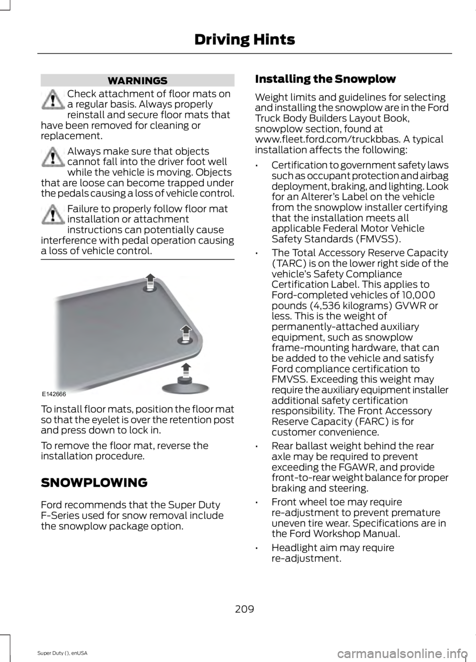
a loss of vehicle control. To install floor mats, position the floor mat
so that the eyelet is over the retention post
and press down to lock in.
To remove the floor mat, reverse the
installation procedure.
SNOWPLOWING
Ford recommends that the Super Duty
F-Series used for snow removal include
the snowplow package option. Installing the Snowplow
Weight limits and guidelines for selecting
and installing the snowplow are in the Ford
Truck Body Builders Layout Book,
snowplow section, found at
www.fleet.ford.com/truckbbas. A typical
installation affects the following:
•
Certification to government safety laws
such as occupant protection and airbag
deployment, braking, and lighting. Look
for an Alterer ’s Label on the vehicle
from the snowplow installer certifying
that the installation meets all
applicable Federal Motor Vehicle
Safety Standards (FMVSS).
• The Total Accessory Reserve Capacity
(TARC) is on the lower right side of the
vehicle ’s Safety Compliance
Certification Label. This applies to
Ford-completed vehicles of 10,000
pounds (4,536 kilograms) GVWR or
less. This is the weight of
permanently-attached auxiliary
equipment, such as snowplow
frame-mounting hardware, that can
be added to the vehicle and satisfy
Ford compliance certification to
FMVSS. Exceeding this weight may
require the auxiliary equipment installer
additional safety certification
responsibility. The Front Accessory
Reserve Capacity (FARC) is for
customer convenience.
• Rear ballast weight behind the rear
axle may be required to prevent
exceeding the FGAWR, and provide
front-to-rear weight balance for proper
braking and steering.
• Front wheel toe may require
re-adjustment to prevent premature
uneven tire wear. Specifications are in
the Ford Workshop Manual.
• Headlight aim may require
re-adjustment.
209
Super Duty (), enUSA Driving HintsE142666