2015 FORD F250 SUPER DUTY battery
[x] Cancel search: batteryPage 145 of 470
On-Board Diagnostics (OBD-II)
Your vehicle is equipped with an on-boarddiagnostics system (OBD-II) that monitorsthe engine’s emission control system. Thissystem protects the environment byensuring that your vehicle continues tomeet government emission standards. TheOBD-II system also assists your authorizeddealer in properly servicing your vehicle.
When the service engine soonindicator illuminates, the OBD-IIsystem has detected amalfunction. Temporary malfunctions maycause the service engine soon indicator toilluminate.
Examples of temporary malfunctions are:
•the vehicle has run out of fuel—theengine may misfire or run poorly
•poor fuel quality or water in thefuel—the engine may misfire or runpoorly
•the fuel fill inlet may not have beenproperly closed See Refueling (page138).
•driving through deep water—theelectrical system may be wet.
You can correct these temporarymalfunctions by filling the fuel tank withgood quality fuel, properly closing the fuelfill inlet or letting the electrical system dryout. After three driving cycles without theseor any other temporary malfunctionspresent, the service engine soon indicatorshould stay off the next time you start theengine. A driving cycle consists of a coldengine startup followed by mixedcity/highway driving. No additional vehicleservice is required.
If the service engine soon indicator remainson, have your vehicle serviced at the firstavailable opportunity. Although somemalfunctions detected by the OBD-II maynot have symptoms that are apparent,continued driving with the service enginesoon indicator on can result in increasedemissions, lower fuel economy, reducedengine and transmission smoothness, andlead to more costly repairs.
Readiness forInspection/Maintenance (I/M)Testing
Some state/provincial and localgovernments may haveInspection/Maintenance (I/M) programsto inspect the emission control equipmenton your vehicle. Failure to pass thisinspection could prevent you from gettinga vehicle registration.
If the service engine soonindicator is on or the bulb doesnot work, you may need to havethe vehicle serviced. See On-BoardDiagnostics (OBD-II).
Your vehicle may not pass the I/M test ifthe service engine soon indicator is on ornot working properly (bulb is burned out),or if the OBD-II system has determinedthat some of the emission control systemshave not been properly checked. In thiscase, your vehicle is not ready for I/Mtesting.
If the vehicle’s engine or transmission hasjust been serviced, or the battery hasrecently run down or been replaced, theOBD-II system may indicate that thevehicle is not ready for I/M testing. Todetermine if the vehicle is ready for I/Mtesting, turn the ignition key to the onposition for 15 seconds without cranking
142
Super Duty (), enUSA
Fuel and Refueling
Page 151 of 470
By moving the gearshift lever from the D(Drive) position to the M (Manual) positionyou may now manually select the gear youdesire. Only the current gear will bedisplayed. Press the + button or the –button to upshift or downshift. If the –button is pressed at a vehicle speed that
would cause an engine overspeed, therequested gear will flash then disappearand the transmission will remain in thecurrent gear.
Recommended shift speeds
Upshift according to the following chart:
Upshifts when accelerating (recommended for best fuel economy)
Diesel enginesGasoline enginesShift from:
12 mph (19 km/h)15 mph (24 km/h)1 – 2
19 mph (31 km/h)25 mph (40 km/h)2 – 3
26 mph (42 km/h)40 mph (64 km/h)3 – 4
34 mph (55 km/h)45 mph (72 km/h)4 – 5
46 mph (74 km/h)50 mph (80 km/h)5 – 6
In order to prevent the engine from runningat too low an RPM, which may cause it tostall, SelectShift will still automaticallymake some downshifts if it has determinedthat you have not downshifted in time.Although SelectShift will make somedownshifts for you, it will still allow you todownshift at any time as long as theSelectShift determines that the engine willnot be damaged from over-revving.
SelectShift will not automatically upshift,even if the engine is approaching the RPMlimit. It must be shifted manually bypressing the + button.
Note:Engine damage may occur ifexcessive engine revving is held withoutshifting.
Automatic Transmission AdaptiveLearning
This feature is designed to increasedurability and provide consistent shift feelover the life of the vehicle. A new vehicleor transmission may have firm shifts, softshifts or both. This operation is considerednormal and will not affect function ordurability of the transmission. Over time,the adaptive learning process will fullyupdate transmission operation.Additionally, whenever the battery isdisconnected or a new battery installed,the strategy must be relearned.
Brake-Shift Interlock
WARNINGS
Do not drive your vehicle until youverify that the brake lamps areworking.
148
Super Duty (), enUSA
Transmission
Page 197 of 470
•Service your vehicle morefrequently if you tow a trailer.See your scheduledmaintenance information.
•If you use a rental trailer, followthe instructions the rentalagency gives you.
See Load limits in the LoadCarrying chapter for loadspecification terms found on thetire label and Safety Compliancelabel and instructions oncalculating your vehicle's load.
Remember to account for thetrailer tongue weight as part ofyour vehicle load when calculatingthe total vehicle weight.
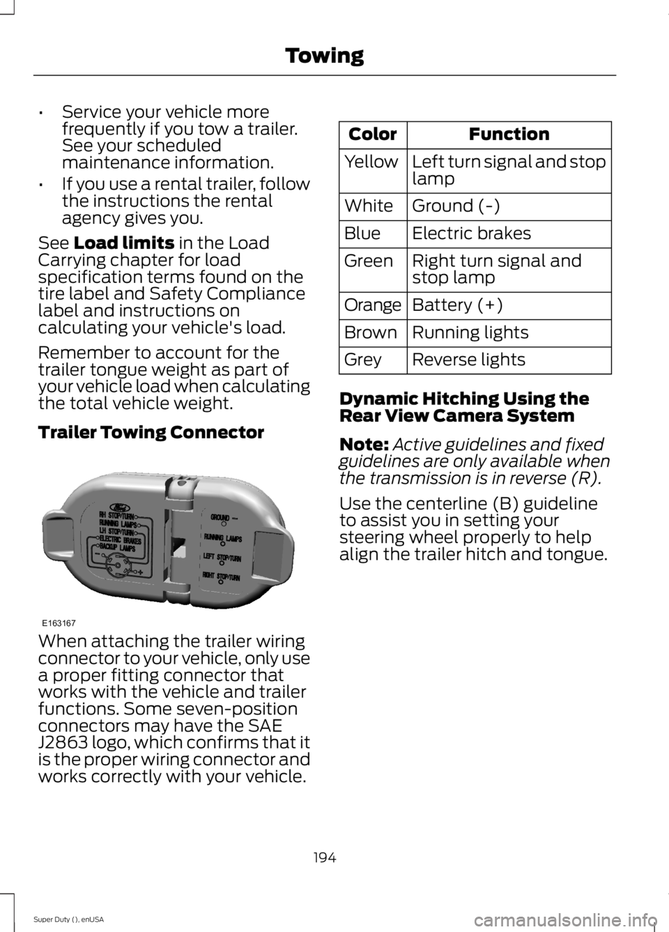
Trailer Towing Connector
When attaching the trailer wiringconnector to your vehicle, only usea proper fitting connector thatworks with the vehicle and trailerfunctions. Some seven-positionconnectors may have the SAEJ2863 logo, which confirms that itis the proper wiring connector andworks correctly with your vehicle.
FunctionColor
Left turn signal and stoplampYellow
Ground (-)White
Electric brakesBlue
Right turn signal andstop lampGreen
Battery (+)Orange
Running lightsBrown
Reverse lightsGrey
Dynamic Hitching Using theRear View Camera System
Note:Active guidelines and fixedguidelines are only available whenthe transmission is in reverse (R).
Use the centerline (B) guidelineto assist you in setting yoursteering wheel properly to helpalign the trailer hitch and tongue.
194
Super Duty (), enUSA
TowingE163167
Page 205 of 470
If the message only displays witha trailer connected, the problemis with the trailer wiring. Consultyour trailer dealer for assistance.This can be a short to ground(such as a chaffed wire), short tovoltage (such as a pulled pin ontrailer emergency breakawaybattery) or the trailer brakes maybe drawing too much current.
Points to Remember
Note:Do not attempt removal ofthe trailer brake controller withoutconsulting the Workshop Manual.Damage to the unit may result.
•Adjust gain setting before usingthe trailer brake controller forthe first time.
•Adjust gain setting, using theprocedure above, wheneverroad, weather and trailer orvehicle loading conditionschange from when the gainwas initially set.
•Only use the manual controllever for proper adjustment ofthe gain during trailer setup.Misuse, such as applicationduring trailer sway, could causeinstability of trailer or towvehicle.
•Avoid towing in adverseweather conditions. The trailerbrake controller does notprovide anti-lock control of thetrailer wheels. Trailer wheelscan lock up on slipperysurfaces, resulting in reducedstability of trailer and towvehicle.
•The trailer brake controller isequipped with a feature thatreduces output at vehiclespeeds below 11 mph (18 km/h)so trailer and vehicle braking isnot jerky or harsh. This featureis only available when applyingthe brakes using your vehicle'sbrake pedal, not the controller.
•The controller interacts withthe brake control system andpowertrain control system ofyour vehicle to provide the bestperformance on different roadconditions.
•Your vehicle's brake systemand the trailer brake systemwork independently of eachother. Changing the gainsetting on the controller doesnot affect the operation of yourvehicle's brakes whether youattach a trailer or not.
202
Super Duty (), enUSA
Towing
Page 215 of 470
ROADSIDE ASSISTANCE
Vehicles Sold In The U.S.: GettingRoadside Assistance
To fully assist you should you have avehicle concern, Ford Motor Companyoffers a complimentary roadsideassistance program. This program isseparate from the New Vehicle LimitedWarranty. The service is available:
•24 hours, seven days a week.
•for the coverage period listed on theRoadside Assistance Card included inyour Owner's Manual portfolio.
Roadside assistance will cover:
•a flat tire change with a good spare, ifprovided with the vehicle (exceptvehicles that have been supplied witha tire inflation kit).
•battery jump start.
•lock-out assistance (key replacementcost is the customer's responsibility).
•fuel delivery — Independent ServiceContractors, if not prohibited by state,local or municipal law, shall deliver upto 2.0 gallons (7.5 liters) of gasoline or5.0 gallons (18.9 liters) of diesel fuelto a disabled vehicle. Fuel deliveryservice is limited to two no-chargeoccurrences within a 12-month period.
•winch out — available within 100 feet(30.5 meters) of a paved or countymaintained road, no recoveries.
•towing — Ford and Lincoln eligiblevehicles towed to an authorized dealerwithin 35 miles (56.3 kilometers) of thedisablement location or to the nearestauthorized dealer. If a memberrequests to be towed to an authorizeddealer more than 35 miles (56.3kilometers) from the disablementlocation, the member shall beresponsible for any mileage costs inexcess of 35 miles (56.3 kilometers).
Trailers shall be covered up to $200 if thedisabled eligible vehicle requires service atthe nearest authorized dealer. If the traileris disabled, but the towing vehicle isoperational, the trailer does not qualify forany roadside services.
Vehicles Sold In The U.S. : UsingRoadside Assistance
Complete the roadside assistanceidentification card and place it in yourwallet for quick reference. This card isfound in the owner's information portfolioin the glove compartment.
U.S. Ford vehicle customers who requireRoadside Assistance, call 1-800-241-3673.
If you need to arrange roadside assistancefor yourself, Ford Motor Company willreimburse a reasonable amount for towingto the nearest dealership within 35 miles(56.3 kilometers). To obtainreimbursement information, U.S. Fordvehicle customers call 1-800-241-3673.Customers will be asked to submit theiroriginal receipts.
Vehicles Sold In Canada : GettingRoadside Assistance
Canadian customers who require roadsideassistance, call 1-800-665-2006.
Vehicles Sold In Canada : UsingRoadside Assistance
For your convenience, you may completethe roadside assistance identification cardfound in the centerfold of your warrantyguide and retain for future reference.
Canadian roadside coverage and benefitsmay differ from the U.S. coverage. If yourequire more information, please refer tothe coverage section of your warrantyguide, call us in Canada at1-800-665-2006, or visit our website atwww.ford.ca.
212
Super Duty (), enUSA
Roadside Emergencies
Page 216 of 470
HAZARD WARNING FLASHERS
Note:The hazard warning flashers willoperate when the ignition is in any positionor if the key is not in the ignition. If usedwhen the engine is not running, the batterywill lose charge. As a result, there may beinsufficient power to restart your engine.
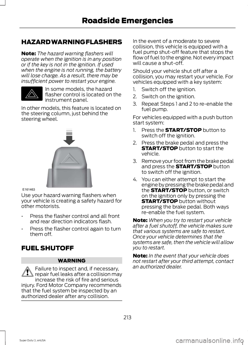
In some models, the hazardflasher control is located on theinstrument panel.
In other models, this feature is located onthe steering column, just behind thesteering wheel.
Use your hazard warning flashers whenyour vehicle is creating a safety hazard forother motorists.
•Press the flasher control and all frontand rear direction indicators flash.
•Press the flasher control again to turnthem off.
FUEL SHUTOFF
WARNING
Failure to inspect and, if necessary,repair fuel leaks after a collision mayincrease the risk of fire and seriousinjury. Ford Motor Company recommendsthat the fuel system be inspected by anauthorized dealer after any collision.
In the event of a moderate to severecollision, this vehicle is equipped with afuel pump shut-off feature that stops theflow of fuel to the engine. Not every impactwill cause a shut-off.
Should your vehicle shut off after acollision, you may restart your vehicle. Forvehicles equipped with a key system:
1. Switch off the ignition.
2. Switch on the ignition.
3. Repeat Steps 1 and 2 to re-enable thefuel pump.
For vehicles equipped with a push buttonstart system:
1. Press the START/STOP button toswitch off the ignition.
2. Press the brake pedal and press theSTART/STOP button to start thevehicle.
3.Remove your foot from the brake pedaland press the START/STOP buttonto switch off the ignition.
4. You can either attempt to start theengine by pressing the brake pedal andthe START/STOP button, or switchon the ignition only by pressing theSTART/STOP button withoutpressing the brake pedal. Both waysre-enable the fuel system.
Note:When you try to restart your vehicleafter a fuel shutoff, the vehicle makes surethat various systems are safe to restart.Once your vehicle determines that thesystems are safe, then the vehicle will allowyou to restart.
Note:In the event that your vehicle doesnot restart after your third attempt, contactan authorized dealer.
213
Super Duty (), enUSA
Roadside EmergenciesE142663 E161463
Page 217 of 470
JUMP STARTING THE VEHICLE
WARNINGS
The gases around the battery canexplode if exposed to flames, sparks,or lit cigarettes. An explosion couldresult in personal injury or vehicle damage.
Batteries contain sulfuric acid whichcan burn skin, eyes and clothing, ifcontacted.
Use only an adequate-sized cablewith insulated clamps.
Preparing Your Vehicle
Note:Do not attempt to push-start yourautomatic transmission vehicle. Automatictransmissions do not have push-startcapability. Attempting to push-start avehicle with an automatic transmission maycause transmission damage.
Note:Use only a 12-volt supply to start yourvehicle.
Note:Do not disconnect the battery of thedisabled vehicle as this could damage thevehicle's electrical system.
Park the booster vehicle close to the hoodof the disabled vehicle, making sure thetwo vehicles do not touch. Turn allaccessories off.
Connecting the Jumper Cables
WARNING
Do not attach the cables to fuel lines,engine rocker covers, the intakemanifold or electrical componentsas grounding points. Stay clear of movingparts. To avoid reverse polarityconnections, make sure that you correctlyidentify the positive (+) and negative (-)terminals on both the disabled and boostervehicles before connecting the cables.
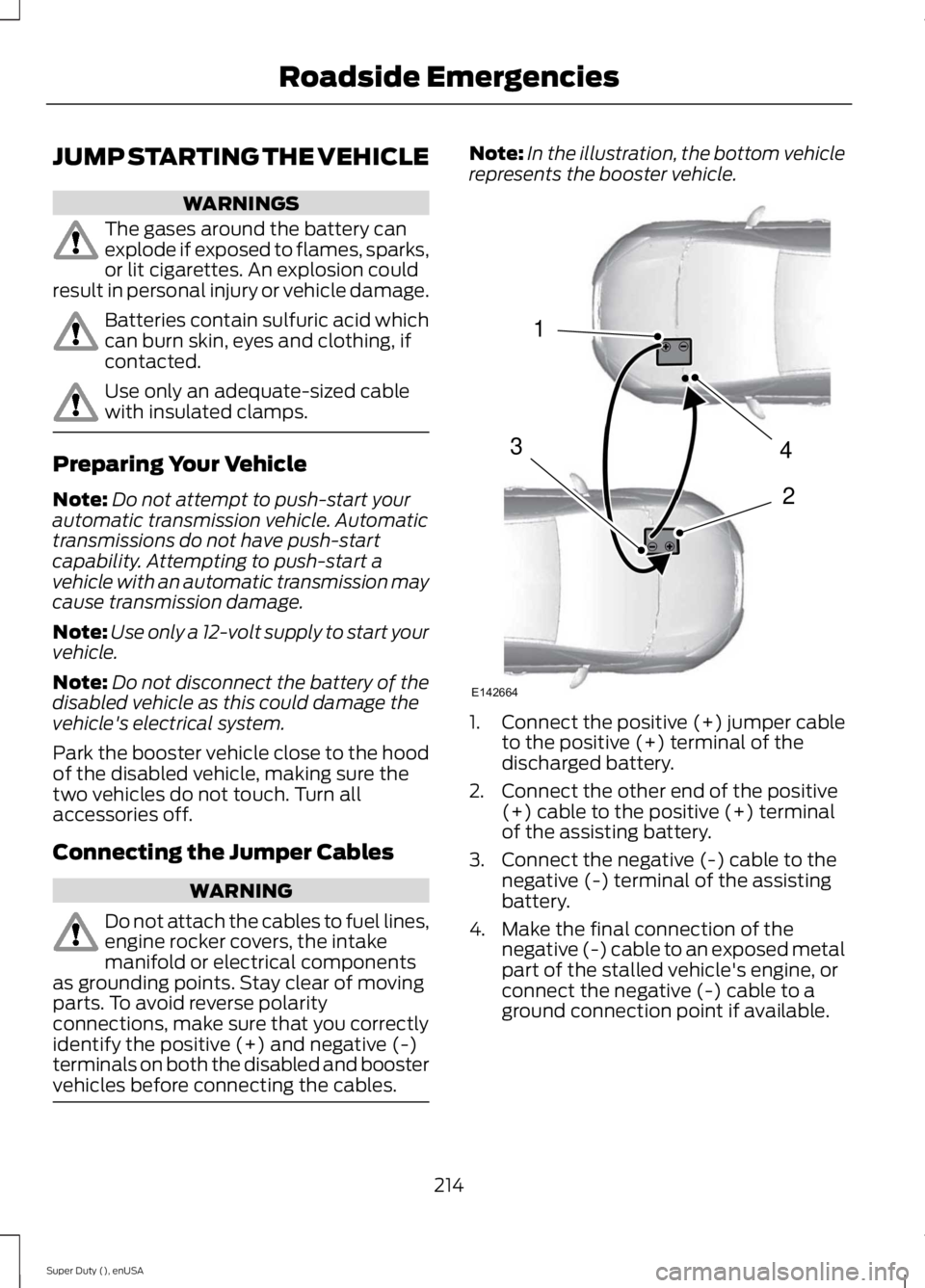
Note:In the illustration, the bottom vehiclerepresents the booster vehicle.
1.Connect the positive (+) jumper cableto the positive (+) terminal of thedischarged battery.
2. Connect the other end of the positive(+) cable to the positive (+) terminalof the assisting battery.
3. Connect the negative (-) cable to thenegative (-) terminal of the assistingbattery.
4. Make the final connection of thenegative (-) cable to an exposed metalpart of the stalled vehicle's engine, orconnect the negative (-) cable to aground connection point if available.
214
Super Duty (), enUSA
Roadside Emergencies4
2
1
3
E142664
Page 218 of 470
WARNING
Do not connect the end of thesecond cable to the negative (-)terminal of the battery to be jumped.A spark may cause an explosion of thegases that surround the battery.
Jump Starting
1.Start the engine of the booster vehicleand rev the engine moderately, or pressthe accelerator gently to keep yourengine speed between 2000 and 3000rpms, as shown in your tachometer.
2.Start the engine of the disabled vehicle.
3. Once the disabled vehicle has beenstarted, run both vehicle engines for anadditional three minutes beforedisconnecting the jumper cables.
Removing the Jumper Cables
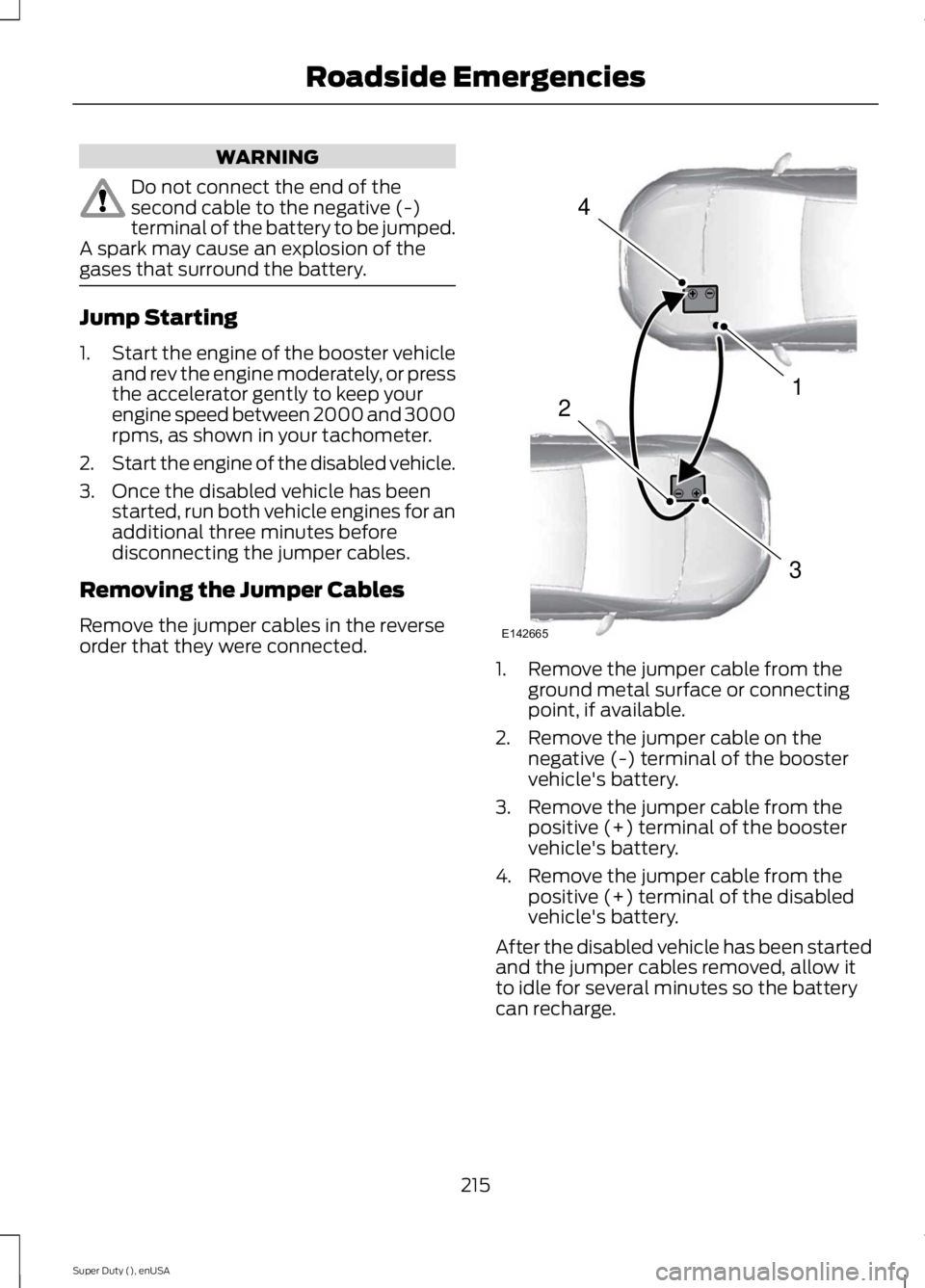
Remove the jumper cables in the reverseorder that they were connected.1. Remove the jumper cable from theground metal surface or connectingpoint, if available.
2. Remove the jumper cable on thenegative (-) terminal of the boostervehicle's battery.
3. Remove the jumper cable from thepositive (+) terminal of the boostervehicle's battery.
4. Remove the jumper cable from thepositive (+) terminal of the disabledvehicle's battery.
After the disabled vehicle has been startedand the jumper cables removed, allow itto idle for several minutes so the batterycan recharge.
215
Super Duty (), enUSA
Roadside Emergencies4
1
3
2
E142665