2015 FORD C MAX lights
[x] Cancel search: lightsPage 235 of 469

Trade number
Function
9005LL
Headlamps high beam (Halogen)
H11LL
Headlamp low beam (Halogen)
168
Sidemarker - front
194
Park lamp - front
W21W
Turn lamp - front
H10 (9145)
Fog lamps
3157K
Tail/brake lamp
T20
Turn lamp - rear
921
Backup lamp
W5W
License plate lamp
W5W
* High-mount brake lamp
LED
* Interior lamps
* To replace these lamps - see your authorized dealer.
To replace all instrument panel lights - see your authorized dealer
232
C-MAX (CCG) Canada/United States of America, enUSA, Second Printing Maintenance
Page 247 of 469

General Information
WARNING
Failure to follow these guidelines
could result in an increased risk of
loss of vehicle control, injury or death.
Note:
Do not use the kit to repair a severely
damaged tire, damaged from driving the
vehicle with a tire that has insufficient air
pressure. You can only use the kit to seal
punctured areas located within the tire
tread.
Do not attempt to repair punctures larger
than 1.4 inch (6.4 millimeters) or damage
to the tire's sidewall. The tire may not
completely seal.
Loss of air pressure may adversely affect
tire performance. For this reason:
Note: Do not drive the vehicle above 50
mph (80 km/h).
Note: Do not drive further than 120 miles
(200 kilometers). Drive only to the closest
Ford Motor Company authorized dealer or
tire repair shop to have your tire inspected.
• Drive carefully and avoid abrupt
steering maneuvers.
• Periodically monitor tire inflation
pressure in the affected tire; if the tire
is losing pressure, have the vehicle
towed.
• Read the information in the Tips for
Use of the Kit section to make sure of
safe operation of the kit and your
vehicle.
Tips for Use of the Kit
Read the following list of tips to make sure
of safe operation of the kit: •
Before operating the kit, make sure
your vehicle is safely off the road and
away from moving traffic. Turn on the
hazard lights.
• Always set the parking brake to make
sure the vehicle does not move
unexpectedly.
• Do not remove any foreign objects,
such as nails or screws, from the tire.
• When using the kit, leave the engine
running (only if the vehicle is outdoors
or in a well-ventilated area) so the
compressor does not drain the
vehicle's battery.
• Do not allow the compressor to
operate continuously for more than 15
minutes; this will help prevent the
compressor from overheating.
• Never leave the kit unattended when
it is operating.
• Sealant compound contains latex.
Make sure that you use the non-latex
gloves provided to avoid an allergic
reaction.
• Keep the kit away from children.
• Only use the kit when the ambient
temperature is between -22°F (– 30°C)
and 158°F (70°C).
• Only use the sealing compound before
the use by date. The use by date is on
the lower right hand corner of the label
located on the sealant canister
(bottle). Check the use by date
regularly and replace the canister after
four years.
• Do not store the kit unsecured inside
the passenger compartment of the
vehicle as it may cause injury during a
sudden stop or crash. Always store the
kit in its original location.
• After sealant use, you must replace the
tire pressure monitoring system sensor
and valve stem on the wheel by an
authorized Ford dealer.
244
C-MAX (CCG) Canada/United States of America, enUSA, Second Printing Wheels and Tires
Page 248 of 469

•
When inflating a tire or other objects,
use the black air hose only. Do not use
the transparent hose, which is designed
for sealant application only.
• Operating the kit could cause an
electrical disturbance in radio, CD, and
DVD player operation.
What to Do When a Tire Is
Punctured
Repair a tire puncture within the tread area
of the tire in two stages with the kit.
• In the first stage, you will re-inflate the
tire with a sealing compound and air.
After the tire has been re-inflated, drive
the vehicle a short distance (about 4
miles [6 kilometers]) to distribute the
sealant in the tire.
• In the second stage, check the tire
pressure and adjust, if necessary, to the
vehicle's tire inflation pressure.
First Stage: Reinflating the Tire
with Sealing Compound and Air WARNINGS
Do not stand directly over the kit
while inflating the tire. If you notice
any unusual bulges or deformations
in the tire's sidewall during inflation, stop
and call roadside assistance. If the tire does not inflate to the
recommended tire pressure within
15 minutes, stop and call roadside
assistance. Preparation: Park the vehicle in a safe, level
and secure area, away from moving traffic.
Turn the hazard lights on. Apply the parking
brake and turn the engine off. Inspect the
flat tire for visible damage.
Sealant compound contains latex. To
avoid any allergic reactions, use the
non-latex gloves located in the accessory
box on the underside of the kit housing. Do not remove any foreign object that has
pierced the tire. If a puncture is located in
the tire sidewall, stop and call roadside
assistance.
1. Remove the valve cap from the tire
valve.
2. Unwrap the clear tube from the compressor housing.
3. Remove the tube cap and fasten the metal connector of the tube to the tire
valve, turning clockwise. Make sure you
fasten the connection tightly. 4. Plug the power cable into the 12-volt
power point in the vehicle.
5. Remove the warning sticker found on the canister, and place it on the top of
the instrument panel or the center of
the dash.
6. Start the vehicle only if the vehicle is outdoors or in a well-ventilated area. 245
C-MAX (CCG) Canada/United States of America, enUSA, Second Printing Wheels and TiresE144619 E144924
Page 253 of 469

•
Read all instructions and cautions fully.
• Before operating the kit, make sure
your vehicle is safely off the road and
away from moving traffic. Switch on
the hazard lights.
• Always set the parking brake to make
sure the vehicle does not move
unexpectedly.
• Do not remove any foreign objects,
such as nails or screws, from the tire.
• When using the kit, leave the engine
running (only if the vehicle is outdoors
or in a well-ventilated area) so the
compressor does not drain the
vehicle's battery.
• Do not allow the compressor to
operate continuously for more than 15
minutes. This will help prevent the
compressor from overheating.
• Never leave the kit unattended during
operation.
• Sealant compound contains latex.
Those with latex sensitivities should
use appropriate precautions to avoid
an allergic reaction.
• Keep the kit away from children.
• Only use the kit when the ambient
temperature is between -22°F (-30°C)
and 158°F (70°C).
• Only use the sealing compound before
the use-by date. The use-by date is on
a label on the sealant canister, which
you can see through the rectangular
viewing window on the bottom of the
compressor. Check the use-by date
regularly and replace the canister after
four years of non-use.
• Do not store the kit unsecured inside
the passenger compartment of the
vehicle as it may cause injury during a
sudden stop or crash. Always store the
kit in its original location. •
After sealant use, an authorized Ford
dealer must replace the tire pressure
monitoring system sensor and valve
stem on the wheel.
• Operating the kit could cause an
electrical disturbance in radio, CD and
DVD player operation. * When inflation only is required
for a tire or other objects, the
selector must be in the Air
position.
What to Do When a Tire Is
Punctured
Repair a tire puncture within the tire's tread
area in two stages with the kit.
• In the first stage, inflate the tire with a
sealing compound and air. After you
inflate the tire, you will need to drive
the vehicle a short distance (about 4
miles [6 kilometers]) to distribute the
sealant in the tire.
• In the second stage, check the tire
pressure and adjust, if necessary, to the
vehicle's specified tire inflation
pressure.
First Stage: Inflating the Tire with
Sealing Compound and Air WARNINGS
Do not stand directly over the kit
while inflating the tire. If you notice
any unusual bulges or deformations
in the tire's sidewall during inflation, stop
and call roadside assistance. If the tire does not inflate to the
recommended tire pressure within
15 minutes, stop and call roadside
assistance. Do not run the engine during kit
operation unless the vehicle is
outdoors or in a well-ventilated area.
250
C-MAX (CCG) Canada/United States of America, enUSA, Second Printing Wheels and TiresE175978
Page 254 of 469

Preparation: Park the vehicle in a safe, level
and secure area, away from moving traffic.
Switch the hazard lights on. Apply the
parking brake and switch the engine off.
Inspect the flat tire for visible damage.
Sealant compound contains latex. Use
appropriate precautions to avoid any
allergic reactions.
Do not remove any foreign object that has
pierced the tire. If a puncture is located in
the tire sidewall, stop and call roadside
assistance.
1. Remove the valve cap from the tire
valve.
2. Unwrap the dual purpose hose (black tube) from the back of the compressor
housing.
3. Fasten the hose to the tire valve by turning the connector clockwise.
Tighten the connection securely. 4. Plug the power cable into the 12-volt
power point in the vehicle.
5. Remove the warning sticker found on the canister and place it on the top of
the instrument panel or the center of
the dash.
6. Start the vehicle and leave the engine running so the compressor does not
drain the vehicle ’s battery. 7. Turn dial (A) clockwise to the sealant
position. Switch the kit on by pressing
the on/off button (B).
8. Inflate the tire to the pressure listed on
the tire label located on the driver door
or the door jamb area. The initial air
pressure gauge reading may indicate
a value higher than the label pressure
while you pump the sealing compound
into the tire. This is normal and should
be no reason for concern. The pressure
251
C-MAX (CCG) Canada/United States of America, enUSA, Second Printing Wheels and TiresE175979 E175981
Page 384 of 469

The system also alerts you to any conflicts
by highlighting areas of the screen in
yellow. If your battery cannot have a full
charge by the scheduled drive time, the
system highlights your next GO Time and
Charge Complete time and a message
Charge at GO Time: under 100%
appears. This is normal; the vehicle is
informing you of the conflicting situation.
This notification only displays when the
gearshift selector lever is in position P.
Note: Charging occurs as soon as you plug
the vehicle in. The system limits cabin
conditioning to 15 minutes before your GO
Time.
To eliminate the conflict notification
immediately or to prevent a conflict in the
future, try the following:
• Change the present GO Time to occur
later.
• Plug the vehicle into a 240V charging
station instead of the 120V
convenience cord. Higher power
charging yields shorter charge times.
• Plug the vehicle in sooner.
Estimated Charge Time Limits
Battery
This shows you the battery's current
charge displayed as a percentage. A
reading of 100% means the battery has a
full charge. A reading of 0% indicates the
battery has no plug-in energy left.
To fully charge
240V
is the estimated minimum charging
time from the present high-voltage battery
level to full charge (100%). This represents
the shortest amount of time you should
expect the high-voltage battery to
recharge under ideal conditions. Ideal
conditions include a 240V charging station
and a minimum 30A service and
high-voltage battery at a moderate
temperature. Note:
This charging time is only an
estimate. It is normal for your actual charge
duration to be longer.
Note: Some charging stations use lower
voltage (208V), which result in longer
charge times.
120V
is the estimated maximum charging
time from the present high-voltage battery
level to full charge (100%). This represents
the longest amount of time you should
expect the high-voltage battery to
recharge under normal conditions. Normal
conditions include a 120V convenience
cord and 12A service.
Note: This charging time is only an
estimate. It is possible for your actual charge
duration to be longer. This occurs when the
AC line voltage is low and may indicate your
electrical source is not meeting certain
requirements. See
Charging the High
Voltage Battery (page 151).
Value Charge Profile and Mode
Value Charge Profile Name
This is the name of the presently detected
Value Charge Profile. The system detects
a customer defined value charge profile
when the vehicle is within approximately
300 feet (100 meters) of the GPS location
registered for the profile. If the vehicle is
close to more than one charge profile, it
chooses the closest. When the vehicle is
not at a defined profile, it uses the Default
Value
charge profile. The system normally
displays Default Profile while you are
driving because the vehicle is typically
between defined value charge profiles.
Edit
Touch this button to access your Value
Charge profiles settings screen (see Value
Charge Profiles
later in this section).
381
C-MAX (CCG) Canada/United States of America, enUSA, Second Printing MyFord Touch
™
(If Equipped)
Page 388 of 469

Power
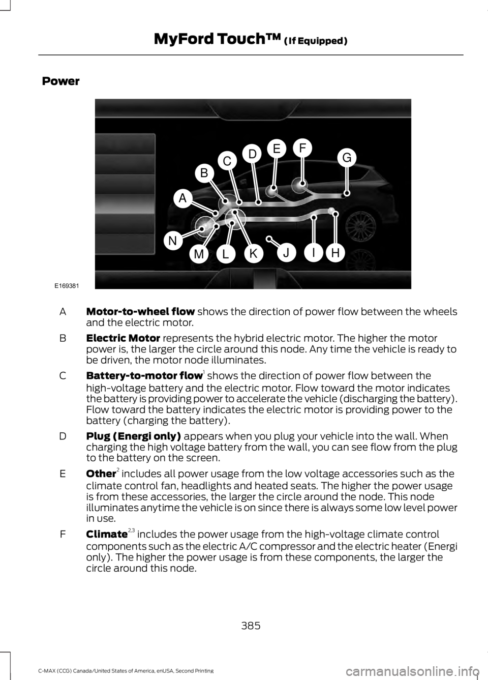
Motor-to-wheel flow shows the direction of power flow between the wheels
and the electric motor.
A
Electric Motor
represents the hybrid electric motor. The higher the motor
power is, the larger the circle around this node. Any time the vehicle is ready to
be driven, the motor node illuminates.
B
Battery-to-motor flow 1
shows the direction of power flow between the
high-voltage battery and the electric motor. Flow toward the motor indicates
the battery is providing power to accelerate the vehicle (discharging the battery).
Flow toward the battery indicates the electric motor is providing power to the
battery (charging the battery).
C
Plug (Energi only)
appears when you plug your vehicle into the wall. When
charging the high voltage battery from the wall, you can see flow from the plug
to the battery on the screen.
D
Other 2
includes all power usage from the low voltage accessories such as the
climate control fan, headlights and heated seats. The higher the power usage
is from these accessories, the larger the circle around the node. This node
illuminates anytime the vehicle is on since there is always some low level power
in use.
E
Climate 2,3
includes the power usage from the high-voltage climate control
components such as the electric A/C compressor and the electric heater (Energi
only). The higher the power usage is from these components, the larger the
circle around this node.
F
385
C-MAX (CCG) Canada/United States of America, enUSA, Second Printing MyFord Touch
™
(If Equipped)A
H
DGEF
BC
IKMLJ
E169381
N
Page 389 of 469

High voltage battery power represents your high-voltage battery. A circle
illuminates around the node when the high-voltage battery is receiving power
from regenerative braking, engine charging or external charging (when you plug
it in). The higher the power going into the high-voltage battery, the larger the
circle around this node.
G
Fuel
represents the fuel tank in the vehicle.
H
Fuel-to-engine flow
shows flow from the fuel tank to the engine when the
engine is on and using fuel (there are some cases where the engine is on, but
not using any fuel). When the engine is on, but not using fuel, the engine node
is active, but the fuel flow path is off. An example of this is when your foot is
off the accelerator pedal and the vehicle is traveling at a high speed.
I
Engine On due to
provides you with the reason(s) the gasoline engine is on.
When the gasoline engine is off, this display does not appear. Engine On due
to
reasons displayed by the system are in a chart following this list.
J
Motor-to-engine flow
shows the direction of power flow between the engine
and the electric motor. The direction indicates if the engine is providing power
to the high-voltage electrical system, or if the high-voltage electrical system is
providing power to control or start the engine.
K
Engine power
represents the gasoline engine. It illuminates only when the
gasoline engine is on. The higher the engine power is, the larger the circle around
this node.
L
Engine-to-wheels flow
shows the direction of the power flow between the
engine and the wheels.
M
Drive power
represents the power going to the wheels. The higher the wheel
power is, the larger the circle around this node. When the engine is off, drive
power is shown in blue. When the engine is on, drive power is shown in grey.
N
1 The battery-to-motor flow includes
battery power the vehicle is using for
acceleration. It does not include energy the
vehicle is using for accessories (such as air
conditioning, headlights and radio). This
screen displays accessories and climate
usage separately. 2
Accessories
indicates electrical power
demands from your vehicle ’s accessory
systems. Accessories use power but do not
contribute to making the vehicle move. The
power flow displays power usage from the
climate control system and other
accessories separately.
3 The climate control system may
determine A/C is necessary even when you
turn it off. In this case, you may see some
climate power when the A/C is off.
386
C-MAX (CCG) Canada/United States of America, enUSA, Second Printing MyFord Touch
™
(If Equipped)