Page 17 of 227
13
SAFETY
DEVICESCORRECT USE
OF THE VEHICLE WARNING
LIGHTS AND
MESSAGESIN AN
EMERGENCYVEHICLE
MAINTENANCETECHNICAL
SPECIFICATIONSINDEX DASHBOARD
AND CONTROLS
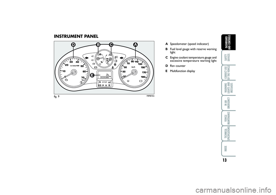
INSTRUMENT PANEL
ASpeedometer (speed indicator)
BFuel level gauge with reserve warning
light
CEngine coolant temperature gauge and
excessive temperature warning light
DRev counter
EMultifunction display
F0P0815m
fig. 9
001-019 SCUDO LUM GB 27/03/14 10:10 Pagina 13
Page 18 of 227
INSTRUMENTS Instrument background color and type
may vary according to the version.
SPEEDOMETER fig. 10
It shows the engine speed.REV. COUNTER fig. 11/a
Rev counter shows engine rpm.
IMPORTANT The electronic injection con-
trol system gradually shuts off the flow of
fuel when the engine is “over-revving” re-
sulting in a gradual loss of engine power.
When the engine is idling, the rev counter
may indicate a gradual or sudden higher-
ing of the speed.
This is normal and takes place for exam-
ple when activating the climate control
system or the fan. In these events a slight
increase in engine idling preserves the bat-
tery charge.
14SAFETY
DEVICESCORRECT USE
OF THE VEHICLE
WARNING
LIGHTS AND
MESSAGESIN AN
EMERGENCYVEHICLE
MAINTENANCETECHNICAL
SPECIFICATIONSINDEXDASHBOARD
AND CONTROLS
fig. 11/a
F0P0014m
fig. 10
F0P0816m
001-019 SCUDO LUM GB 27/03/14 10:10 Pagina 14
Page 19 of 227

15
SAFETY
DEVICESCORRECT USE
OF THE VEHICLE WARNING
LIGHTS AND
MESSAGESIN AN
EMERGENCYVEHICLE
MAINTENANCETECHNICAL
SPECIFICATIONSINDEX DASHBOARD
AND CONTROLS
FUEL LEVEL GAUGE B-fig. 11/b
This shows the amount of fuel left in the
fuel tank.K
tank full (See the indications given in
paragraph “At the filling station”).
åtank empty.
The reserve warning light Kturns on to
indicate that approximately 7 litres of fu-
el are left in the tank.
Do not travel with the fuel tank almost
empty: the gaps in fuel delivery could dam-
age the catalyst.ENGINE COOLANT
TEMPERATURE GAUGE
C-fig. 11/b
This shows the temperature of the engine
coolant fluid and begins working when the
fluid temperature exceeds approx. 50°C.
Under normal conditions, the needle
should hover around the middle of the
scale according to the working conditions.
åLow engine coolant temperature.
u
High engine coolant temperature.If the needle reaches the red
area, stop the engine imme-
diately and contact a Fiat
Dealership.
fig. 11/b
1/2
F0P0320m
001-019 SCUDO LUM GB 27/03/14 10:10 Pagina 15
Page 20 of 227

16SAFETY
DEVICESCORRECT USE
OF THE VEHICLE
WARNING
LIGHTS AND
MESSAGESIN AN
EMERGENCYVEHICLE
MAINTENANCETECHNICAL
SPECIFICATIONSINDEXDASHBOARD
AND CONTROLS
Warning lights on the upper plate
On certain versions, the upper plate
fig. 12(located above the driving mirror)
can be fitted with the following warning
lights:❒
warning light indicating that the seat
belt is not fastened (<) (version with
two front seats).
❒
warning light indicating that the pas-
senger air bag is off (
“
)
INSTRUMENT PANEL
BRIGHTNESS ADJUSTER
To adjust the instrument panel brightness:
press button A-fig. 13
fig. 12
F0P0285m
DISPLAY The display fig. 14shows by the relevant
warning lights (see section “Warning lights
and messages”):❒
speed limiter / control;
❒
total km / mi covered;
❒
engine oil level gauge;
❒
water in diesel fuel filter;
❒
glow plug preheating.
According to versions the display shows
the time. Setting the clock through the
instrument panel display
To set the clock through the instrument pan-
el display, use button A-fig. 15as follows:
❒
turning the button leftwards makes the
minute value flash;
❒
turning the button rightwards will in-
crease minute value (keep the button
turned rightwards to speed up rolling);
❒
turning the button leftwards makes the
hour value flash;
❒
turning the button rightwards will in-
crease hour value (keep the button
turned rightwards to speed up rolling);
❒
turning the button leftwards selects
24H or 12H mode display;
fig. 14
F0P0291m
fig. 13
1/2
F0P0353m
001-019 SCUDO LUM GB 27/03/14 10:10 Pagina 16
Page 21 of 227

17
SAFETY
DEVICESCORRECT USE
OF THE VEHICLE WARNING
LIGHTS AND
MESSAGESIN AN
EMERGENCYVEHICLE
MAINTENANCETECHNICAL
SPECIFICATIONSINDEX DASHBOARD
AND CONTROLS
❒
turn the button rightwards to select the
required mode;
❒
turn the button leftwards to stop clock
setting.
If no other setting is made, after about 30
seconds the display will show the time ac-
cording to the selected settings.
Setting the clock through the
display on the central console
Certain versions are fitted with a central
console with a display showing the time.
To set the clock consult the trip comput-
er under option “Set clock and date”.
GEAR SHIFT
INDICATORThe “GSI” (Gear Shift Indicator) system
advises the driver to change gear through
a special indication on the display fig. 15/a.
Through the GSI, the driver is notified that
the gear change will allow a reduction in
fuel consumption.
When the ▲(SHIFT UP) icon is shown on
the display, the GSI is advising the driver
to engage a higher gear, while the ▼
(SHIFT DOWN) icon advises the driver
to engage a lower gear.NBThe indication on the instrument pan-
el remains on until the driver changes gear
or until the driving conditions return to
a situation where a gear change is not re-
quired to reduce consumption.
fig. 15/a
F0P0291m
fig. 15
1/2
F0P0292m
001-019 SCUDO LUM GB 27/03/14 10:10 Pagina 17
Page 22 of 227

18SAFETY
DEVICESCORRECT USE
OF THE VEHICLE
WARNING
LIGHTS AND
MESSAGESIN AN
EMERGENCYVEHICLE
MAINTENANCETECHNICAL
SPECIFICATIONSINDEXDASHBOARD
AND CONTROLS
MAINTENANCE
INDICATORIt regulates the intervals between the main-
tenance operations based on vehicle use.
Functioning
As soon as the starting key is inserted and
for a few seconds, the maintenance key lights
up and which indicates the maintenance op-
erations; the total odometer display indicates
the number of kilometres {rounded down}
which can be covered until the next main-
tenance operation. The maintenance expiry
dates are calculated starting from the last re-
setting of the indicator.
This expiry date is determined by means
of two parameters:❒
the distance in kilometres covered
❒
time which has passed since the last
maintenance operation.
The distance in kilometres
which remains to be covered
can be considered by the time
factor, based on the driver’s
driving habits.
F0P0354mF0P0355m
OIL OK
F0P0356m
Maintenance expiry date over
1,000 km
Example: one can still travel 4,800 km be-
fore the next maintenance operation. Af-
ter having turned the starting key to the
Mposition and for a few seconds, the dis-
play indicates:
A few seconds after having turned the
starting key to the Mposition, the oil lev-
el is shown, therefore the total odometer
works again and it indicates the total and
daily amount of kilometres travelled.
Maintenance expiry date less than
1,000 km
After having turned the starting key to the
Mposition and for a few seconds, the
maintenance key flashes and the remain-
ing number of kilometres is shown.ENGINE OIL LEVEL
INDICATOR
Turning the starting key to the
Mposition, the instrument, after having
shown the kilometres to be covered be-
fore the next maintenance operation, sup-
plies the synchronised indication of the oil
level present in the engine oil pan. The
flashing of the word “OIL”, accompanied
by a beeping and by a message, indicates
an insufficient quantity of oil in the engine.
The flashing of the word “OIL –“ indicates
a problem with the engine oil sensor.
Maintenance Expiry date exceeded
After having turned the
starting key to the Mposi-
tion and for a few seconds,
the maintenance key flashes
and the number of kilome-
tres
travelled after the expiry date of the main-
tenance operation is shown.
When the engine is running, the
maintenance key remains
switch until the maintenance
operation has been carried out.
Before the two expiry dates are reached:
the maintenance key lights up also when
the expiry date of two years has been ex-
ceeded.
001-019 SCUDO LUM GB 27/03/14 10:10 Pagina 18
Page 23 of 227

19
SAFETY
DEVICESCORRECT USE
OF THE VEHICLE WARNING
LIGHTS AND
MESSAGESIN AN
EMERGENCYVEHICLE
MAINTENANCETECHNICAL
SPECIFICATIONSINDEX DASHBOARD
AND CONTROLS
Distance to cover
This value shows the distance to be cov-
ered yet, under active navigation condi-
tion.
Trip distance
This value shows the distance covered
from the start of the journey, after reset-
ting (Reset).
Average consumption
This value shows the average consump-
tion from the start of the journey, after
resetting (Reset).
Average speed
This value shows the vehicle average
speed calculated from the start of the
journey, after resetting (Reset).
TRIP COMPUTERThe trip computer enables to display in se-
quence, by pressing repeatedly button
fig. 16set on the top of the steering col-
umn stalk, the following values:
range, instant consumption, distance
to cover, trip 1 (trip distance, aver-
age consumption, average speed)
and trip 2 (trip distance, average
consumption, average speed).
This information is displayed on the dis-
play of the infotelematic CONNECT sys-
tem.
Reset: press button shown in fig. 16for
over 2 seconds for resetting.
Range
This value shows the distance in km (or
mi) that the vehicle can still cover before
needing fuel, assuming that driving condi-
tions are kept unvaried.
Instant consumption
This value shows average fuel consump-
tion calculated during the last seconds of
travel.
fig. 16
F0P0041m
FRONT SEATS
Only make adjustments when
the vehicle is stationary.
WARNING
Fabric upholstery of your Fiat
SCUDO is purpose-made to
withstand common wear re-
sulting from normal use of the
vehicle. It is however absolutely neces-
sary to prevent hard and/or prolonged
scratching/scraping caused by clothing
accessories like metallic buckles, studs,
“Velcro” fixings, etc. that stressing lo-
cally the fabric could break yarns and
damage the upholstery as a conse-
quence.
001-019 SCUDO LUM GB 27/03/14 10:10 Pagina 19
Page 24 of 227

20SAFETY
DEVICESCORRECT USE
OF THE VEHICLE
WARNING
LIGHTS AND
MESSAGESIN AN
EMERGENCYVEHICLE
MAINTENANCETECHNICAL
SPECIFICATIONSINDEX
DASHBOARD
AND
CONTROLS
Moving the seat backwards or
forwards fig. 17
Lift the lever Aand push the seat forwards
or backwards: in the driving position the
arms should rest on the rim of the steer-
ing wheel. Once you have released the
lever, check that the seat is firmly locked
in the runners by trying to move it back
and forth.
Once you have released the
lever, check that the seat is
firmly locked in the runners by trying
to move it back and forth. Failure to
lock the seat in place could result in
the seat moving suddenly and the dri-
ver losing control of the vehicle.
WARNING
For maximum safety, keep
the back of your seat up-
right, lean back into it and make sure
the seat belt fits closely across your
chest and hips.
WARNING
Regulation of the height of the
driver’s seat fig. 17-18
Depending on the version and the configu-
ration of the vehicle, it is equipped with: ❒
a passive regulation: pull lever B
upwards, therefore get off the seat in
order to allow it to rise.
❒
an active regulation: pull lever D
upwards or downwards until the
desired position is desired.
Back rest angle adjustment fig. 17
Use lever C and adjust the back rest.
Do not remove the seats or
carry out servicing and/or re-
pair operations since incorrect oper-
ations could impair the regular op-
eration of safety devices: always con-
tact Fiat Dealership.
WARNING
fig. 17
F0P0015m
fig. 18
F0P0322m
020-082 SCUDO LUM GB 19/11/13 09.53 Pagina 20