2015 FIAT FREEMONT steering
[x] Cancel search: steeringPage 313 of 412

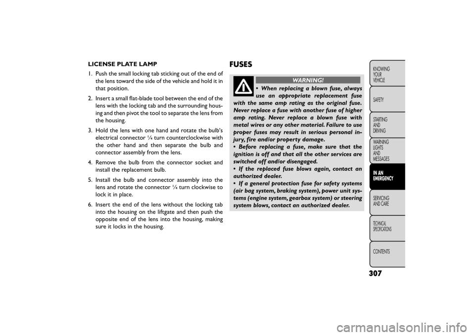
LICENSE PLATE LAMP
1. Push the small locking tab sticking out of the end ofthe lens toward the side of the vehicle and hold it in
that position.
2. Insert a small flat-blade tool between the end of the lens with the locking tab and the surrounding hous-
ing and then pivot the tool to separate the lens from
the housing.
3. Hold the lens with one hand and rotate the bulb's electrical connector ¼ turn counterclockwise with
the other hand and then separate the bulb and
connector assembly from the lens.
4. Remove the bulb from the connector socket and install the replacement bulb.
5. Install the bulb and connector assembly into the lens and rotate the connector ¼ turn clockwise to
lock it in place.
6. Insert the end of the lens without the locking tab into the housing on the liftgate and then push the
opposite end of the lens into the housing, making
sure it locks in the housing.FUSES
WARNING!
• When replacing a blown fuse, always
use an
appropriate replacement fuse
with the same amp rating as the original fuse.
Never replace a fuse with another fuse of higher
amp rating. Never replace a blown fuse with
metal wires or any other material. Failure to use
proper fuses may result in serious personal in-
jury, fire and/or property damage.
• Before replacing a fuse, make sure that the
ignition is off and that all the other services are
switched off and/or disengaged.
• If the replaced fuse blows again, contact an
authorized dealer.
• If a general protection fuse for safety systems
(air bag system, braking system), power unit sys-
tems (engine system, gearbox system) or steering
system blows, contact an authorized dealer.
307
KNOWING
YOUR
VEHICLE
SAFETY
STARTING
AND
DRIVING
WARNING
LIGHTS
AND
MESSAGES
IN AN
EMERGENCY
SER VICING
AND
CARE
TECHNICAL
SPECIFICATIONS
CONTENTS
Page 315 of 412

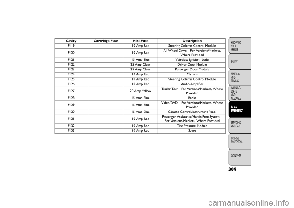
CavityCartridge Fuse Mini-Fuse Description
F119 10 Amp RedSteering Column Control Module
F120 10 Amp RedAll Wheel Drive – For Versions/Markets,
Where Provided
F121 15 Amp BlueWireless Ignition Node
F122 25 Amp ClearDriver Door Module
F123 25 Amp ClearPassenger Door Module
F124 10 Amp RedMirrors
F125 10 Amp RedSteering Column Control Module
F126 10 Amp RedAudio Amplifier
F127 20 Amp YellowTrailer Tow – For Versions/Markets, Where
Provided
F128 15 Amp BlueRadio
F129 15 Amp BlueVideo/DVD – For Versions/Markets, Where
Provided
F130 15 Amp BlueClimate Control/Instrument Panel
F131 10 Amp RedPassenger Assistance/Hands Free System –
For Versions/Markets, Where Provided
F132 10 Amp RedTire Pressure Module
F133 10 Amp RedSpare
309
KNOWING
YOUR
VEHICLE
SAFETY
STARTING
AND
DRIVING
WARNING
LIGHTS
AND
MESSAGES
IN AN
EMERGENCY
SERVICING
AND
CARE
TECHNICAL
SPECIFICATIONS
CONTENTS
Page 318 of 412

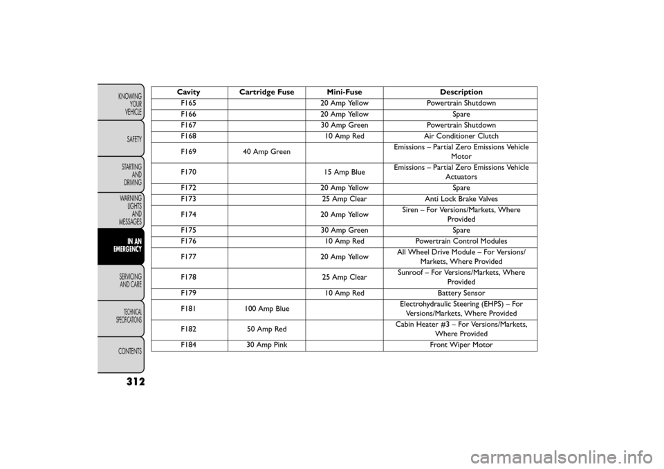
Cavity Cartridge Fuse Mini-FuseDescription
F165 20 Amp YellowPowertrain Shutdown
F166 20 Amp YellowSpare
F167 30 Amp GreenPowertrain Shutdown
F168 10 Amp RedAir Conditioner Clutch
F169 40 Amp Green Emissions – Partial Zero Emissions Vehicle
Motor
F170 15 Amp BlueEmissions – Partial Zero Emissions Vehicle
Actuators
F172 20 Amp YellowSpare
F173 25 Amp ClearAnti Lock Brake Valves
F174 20 Amp YellowSiren – For Versions/Markets, Where
Provided
F175 30 Amp GreenSpare
F176 10 Amp RedPowertrain Control Modules
F177 20 Amp YellowAll Wheel Drive Module – For Versions/
Markets, Where Provided
F178 25 Amp ClearSunroof – For Versions/Markets, Where
Provided
F179 10 Amp RedBattery Sensor
F181 100 Amp Blue Electrohydraulic Steering (EHPS) – For
Versions/Markets, Where Provided
F182 50 Amp Red Cabin Heater #3 – For Versions/Markets,
Where Provided
F184 30 Amp Pink Front Wiper Motor
312
KNOWING
YOUR
VEHICLE
SAFETY
STARTING AND
DRIVING
WARNING LIGHTSAND
MESSAGES
IN AN
EMERGENCY
SER VICING
AND
CARE
TECHNICAL
SPECIFICATIONS
CONTENTS
Page 320 of 412

FREEING A STUCK VEHICLE
If your vehicle becomes stuck in mud, sand, or snow, it
can often be moved using a rocking motion. Turn the
steering wheel right and left to clear the area around
the front wheels. Then shift back and forth between
DRIVE and REVERSE (with automatic transmission) or
2nd gear and REVERSE (with manual transmission),
while gently pressing the accelerator. Use the least
amount of accelerator pedal pressure that will maintain
the rocking motion, without spinning the wheels or
racing the engine.
NOTE:Press the "ESC Off" switch, to place the
Electronic Stability Control (ESC) system in
"Partial Off" mode, before rocking the ve-
hicle. Refer to “Electronic Brake Control” in
“Knowing Your Vehicle” for further informa-
tion. Once the vehicle has been freed, press the "ESC
Off" switch again to restore "ESC On" mode.
• Racing the engine or spinning the
wheels may lead to transmission over-
heating and failure. Allow the engine to
idle with the transmission in NEUTRAL for at
least one minute after every five rocking-motion
cycles.This will minimize overheating and reduce
the risk of clutch or transmission failure during
prolonged efforts to free a stuck vehicle.
• When “rocking” a stuck vehicle by shifting be-
tween DRIVE/2nd gear and REVERSE, do not spin
the wheels faster than 24 km/h, or drivetrain
damage may result .
• Revving the engine or spinning the wheels too
fast may lead to transmission overheating and
failure. It can also damage the tires. Do not spin
the wheels above 48 km/h while in gear (no trans-
mission shifting occurring).
314
KNOWING YOUR
VEHICLE
SAFETY
STARTING AND
DRIVING
WARNING LIGHTSAND
MESSAGES
IN AN
EMERGENCY
SER VICING
AND
CARE
TECHNICAL
SPECIFICATIONS
CONTENTS
Page 325 of 412

•Do not use sling type equipment when
towing.Vehicle damage may occur.
• When securing the vehicle to a flat bed
truck, do not attach to front or rear suspension
components. Damage to your vehicle may result
from improper towing.
• Do not push or tow this vehicle with another
vehicle as damage to the bumper fascia and trans-
mission may result .
• If the vehicle being towed requires steering, the
ignition switch must be in the ACC or ON/RUN
position, not in the LOCK/OFF position.
WITHOUT THE KEY FOB
Special care must be taken when the vehicle is towed
with the ignition in the OFF position. Flatbed towing is
the preferred towing method. However, if a flatbed
towing vehicle is not available, wheel lift towing equip-
ment may be used. Rear towing (with the front wheels
on the ground) is not allowed, as transmission damage
will occur. If rear towing is the only alternative, the
front wheels must be placed on a towing dolly. Proper
towing equipment is necessary to prevent damage to
the vehicle. ALL-WHEEL DRIVE (AWD) MODELS
The manufacturer requires towing with all four wheels
OFF
the ground. Acceptable methods are to tow the
vehicle on a flatbed, or with one end of vehicle raised
and the opposite end on a towing dolly.
Towing this vehicle in violation of the
above requirements can cause severe
transmission and/or power transfer unit
damage. Damage from improper towing is not
covered under the New Vehicle Limited Warranty.
FRONT WHEEL DRIVE (FWD) MODELS —
MANUAL TRANSMISSION
The manufacturer recommends towing your vehicle
with all four wheels OFF the ground using a flatbed.
Your vehicle may also be towed in the forward direc-
tion, with all four wheels on the ground, the transmis-
sion in NEUTRAL, and the ignition in the ACC or
ON/RUN position. If the transmission is not operative,
the vehicle must be towed with the front wheels OFF
the ground (using a flatbed truck, towing dolly, or
wheel lift equipment with the front wheels raised).
319
KNOWING
YOUR
VEHICLE
SAFETY
STARTING
AND
DRIVING
WARNING
LIGHTS
AND
MESSAGES
IN AN
EMERGENCY
SER VICING
AND
CARE
TECHNICAL
SPECIFICATIONS
CONTENTS
Page 330 of 412

Thousands Of Kilometers 15 30 45 60 75 90 105 120 135 150Years 1 2 3 4 5678910
Replace rear drive assembly (RDA) fluid (for
versions/markets, where provided). •
Replace power transfer unit (PTU) fluid (for
versions/markets, where provided). •
Replace cabin filter. (#) ◦•◦ • ◦ •◦•◦•
Flush and replace the engine coolant. •
◦Recommend replacement.
(#) The air cleaner cartridge must be changed every
15,000 km if used in dusty areas.
(##)
Non-dusty/normal areas: advised maximum mileage
120,000 km. Regardless of the mileage, the belt must be
replaced every 6 years. Dusty areas and/or demanding use
(cold climates, town use, long periods of idling): advised
maximum mileage 60,000 km. Regardless of the mileage,
the belt must be replaced every 4 years.
(*)The oil and oil filter replacement must be carried out
when indicated by a warning light or message on the
instrument panel, or in any case should not exceed 1 year.
(**) The spark plug change is km based only, yearly
intervals do not apply.
(***) Change the automatic transmission fluid and
filter(s) at 75,000 km or 5 years if using your vehicle for
police, taxi, fleet, or frequent trailer towing. Periodic Checks
Every
1,000 km or before long journeys, check and, if
necessary, restore:
• engine coolant;
• brake fluid;
• power steering fluid;
• windshield washer fluid level;
• tire inflation pressure and condition;
• operation of lighting system (headlights, direction indicators, hazard warning lights, etc.);
• operation of windshield washer/wiper system and positioning/wear of windshield/rear window wiper
blades.
324
KNOWING YOUR
VEHICLE
SAFETY
STARTING AND
DRIVING
WARNING LIGHTSAND
MESSAGES
IN AN
EMERGENCY
SERVICINGAND C ARE
TECHNICAL
SPECIFICATIONS
CONTENTS
Page 337 of 412

Failure to perform the required mainte-
nance items may result in damage to the
vehicle.
Periodic Checks
Every 1,000 km or before long journeys, check and, if
necessary, restore:
• engine coolant;
• brake fluid;
• power steering fluid;
• windshield washer fluid level;
• tire inflation pressure and condition;
• operation of lighting system (headlights, direction indicators, hazard warning lights, etc.);
• operation of windshield washer/wiper system and positioning/wear of windshield/rear window wiper
blades.
Every 3,000 km, check and top up, if required, the
engine oil level.
Heavy-Duty Use Of The Car
If the car is used mainly under one of the following
conditions:
• towing a trailer or caravan; • dusty roads;
• short, repeated journeys (less than 7-8 km) at sub-
zero outside temperatures;
• engine often idling or driving long distances at low speeds or long periods of idleness.
You should perform the following inspections more
frequently than shown on the Scheduled Servicing Plan:
• check front disc brake pad conditions and wear;
• check cleanliness of hood and trunk locks, cleanli- ness and lubrication of linkage;
• visually inspect conditions of: engine, transmission, pipes and hoses (exhaust - fuel system - brakes) and
rubber elements (boots - sleeves - bushes - etc.);
• check battery charge and battery fluid level (electro- lyte);
• visually inspect condition of the accessory drive belts;
• check and, if necessary, change engine oil and replace oil filter;
• check and, if necessary, replace pollen filter;
• check and, if necessary, replace air cleaner.
331
KNOWING
YOUR
VEHICLE
SAFETY
STARTING
AND
DRIVING
WARNING
LIGHTS
AND
MESSAGES
IN AN
EMERGENCY
SERVICING
AND C ARE
TECHNICAL
SPECIFICATIONS
CONTENTS
Page 338 of 412

ENGINE COMPARTMENT — 2.4L
(fig. 197)
(fig. 197)
1 — Engine Coolant Reservoir7 — Power Distribution Center (Fuses)
2 — Power Steering Fluid Reservoir 8 — Air Cleaner Filter
3 — Engine Oil Fill 9 — Automatic Transmission Dipstick (4–Speed Only)
4 — Brake Fluid Reservoir 10 — Washer Fluid Reservoir
5 — Remote Jump Start (Positive Battery Post) 11 — Coolant Reservoir Cap
6 — Remote Jump Start (Negative Battery Post) 12 — Engine Oil Dipstick
332
KNOWING
YOUR
VEHICLE
SAFETY
STARTING AND
DRIVING
WARNING LIGHTSAND
MESSAGES
IN AN
EMERGENCY
SERVICINGAND C ARE
TECHNICAL
SPECIFICATIONS
CONTENTS