2015 FIAT FREEMONT key
[x] Cancel search: keyPage 128 of 412

To Engage The Child-Protection Door Lock
System
1. Open the rear door.
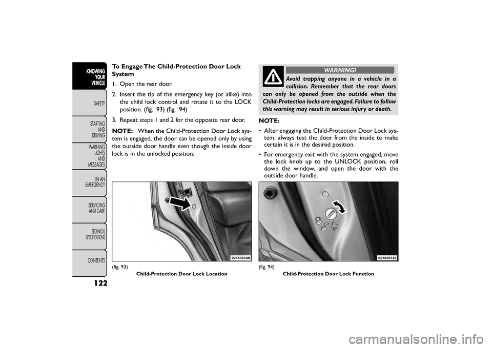
2. Insert the tip of the emergency key (or alike) intothe child lock control and rotate it to the LOCK
position. (fig. 93) (fig. 94)
3. Repeat steps 1 and 2 for the opposite rear door.
NOTE: When the Child-Protection Door Lock sys-
tem is engaged, the door can be opened only by using
the outside door handle even though the inside door
lock is in the unlocked position.WARNING!
Avoid trapping anyone in a vehicle in a
collision. Remember that the rear doors
can only be opened from the outside when the
Child-Protection locks are engaged. Failure to follow
this warning may result in serious injury or death.
NOTE:
• After engaging the Child-Protection Door Lock sys- tem, always test the door from the inside to make
certain it is in the desired position.
• For emergency exit with the system engaged, move the lock knob up to the UNLOCK position, roll
down the window, and open the door with the
outside door handle.
(fig. 93)
Child-Protection Door Lock Location(fig. 94)Child-Protection Door Lock Function
122
KNOWINGYOUR
VEHICLE
SAFETY
STAR
TINGAND
DRIVING
WARNING LIGHTSAND
MESSAGES
IN AN
EMERGENCY
SERVICINGAND CARE
TECHNICAL
SPECIFICATIONS
CONTENTS
Page 129 of 412

To Disengage The Child-Protection Door Lock
System
1. Open the rear door.
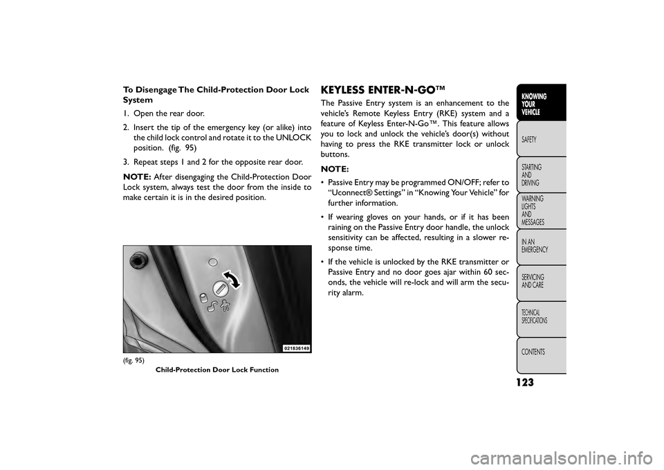
2. Insert the tip of the emergency key (or alike) intothe child lock control and rotate it to the UNLOCK
position. (fig. 95)
3. Repeat steps 1 and 2 for the opposite rear door.
NOTE: After disengaging the Child-Protection Door
Lock system, always test the door from the inside to
make certain it is in the desired position.KEYLESS ENTER-N-GO™
The Passive Entry system is an enhancement to the
vehicle’s Remote Keyless Entry (RKE) system and a
feature of Keyless Enter-N-Go™. This feature allows
you to lock and unlock the vehicle’s door(s) without
having to press the RKE transmitter lock or unlock
buttons.
NOTE:
• Passive Entry may be programmed ON/OFF; refer to “Uconnect® Settings” in “Knowing Your Vehicle” for
further information.
• If wearing gloves on your hands, or if it has been raining on the Passive Entry door handle, the unlock
sensitivity can be affected, resulting in a slower re-
sponse time.
• If the vehicle is unlocked by the RKE transmitter or Passive Entry and no door goes ajar within 60 sec-
onds, the vehicle will re-lock and will arm the secu-
rity alarm.
(fig. 95)
Child-Protection Door Lock Function
123
KNOWING
YOUR
VEHICLE
SAFETY
STAR
TING
AND
DRIVING
WARNING
LIGHTS
AND
MESSAGES
IN AN
EMERGENCY
SERVICING
AND CARE
TECHNICAL
SPECIFICATIONS
CONTENTS
Page 132 of 412

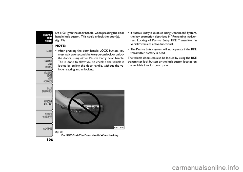
Do NOT grab the door handle, when pressing the door
handle lock button. This could unlock the door(s).
(fig. 99)
NOTE:
• After pressing the door handle LOCK button, youmust wait two seconds before you can lock or unlock
the doors, using either Passive Entry door handle.
This is done to allow you to check if the vehicle is
locked by pulling the door handle, without the ve-
hicle reacting and unlocking. • If Passive Entry is disabled using Uconnect® System,
the key protection described in "Preventing Inadver-
tent Locking of Passive Entry RKE Transmitter in
Vehicle" remains active/functional.
• The Passive Entry system will not operate if the RKE transmitter battery is dead.
The vehicle doors can also be locked by using the RKE
transmitter lock button or the lock button located on
the vehicle’s interior door panel.
(fig. 99) Do NOT Grab The Door Handle When Locking
126
KNOWING YOUR
VEHICLE
SAFETY
STAR
TINGAND
DRIVING
WARNING LIGHTSAND
MESSAGES
IN AN
EMERGENCY
SERVICINGAND CARE
TECHNICAL
SPECIFICATIONS
CONTENTS
Page 133 of 412

WINDOWS
POWER WINDOWS
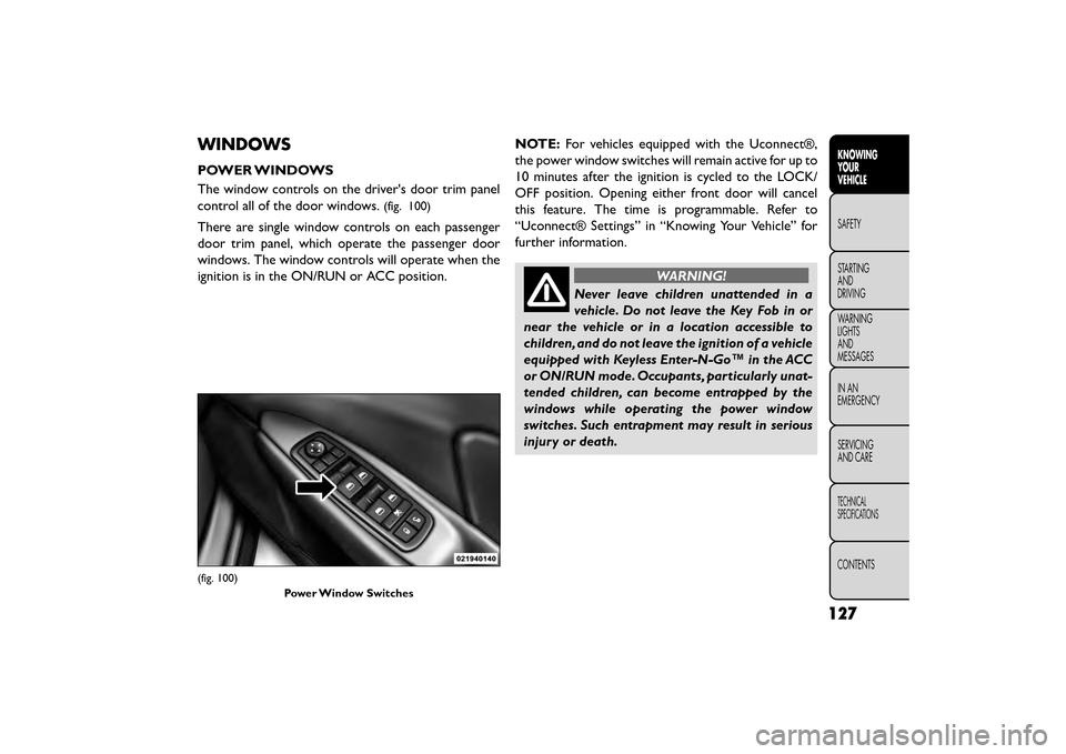
The window controls on the driver's door trim panel
control all of the door windows.
(fig. 100)
There are single window controls on each passenger
door trim panel, which operate the passenger door
windows. The window controls will operate when the
ignition is in the ON/RUN or ACC position.NOTE:
For vehicles equipped with the Uconnect®,
the power window switches will remain active for up to
10 minutes after the ignition is cycled to the LOCK/
OFF position. Opening either front door will cancel
this feature. The time is programmable. Refer to
“Uconnect® Settings” in “Knowing Your Vehicle” for
further information.
WARNING!
Never leave children unattended in a
vehi cle
. Do not leave the Key Fob in or
near the vehicle or in a location accessible to
children, and do not leave the ignition of a vehicle
equipped with Keyless Enter-N-Go™ in the ACC
or ON/RUN mode. Occupants, particularly unat-
tended children, can become entrapped by the
windows while operating the power window
switches. Such entrapment may result in serious
injury or death.
(fig. 100)
Power Window Switches
127
KNOWING
YOUR
VEHICLE
SAFETY
STAR
TING
AND
DRIVING
WARNING
LIGHTS
AND
MESSAGES
IN AN
EMERGENCY
SERVICING
AND CARE
TECHNICAL
SPECIFICATIONS
CONTENTS
Page 136 of 412

LIFTGATE
The liftgate can be unlocked or locked pushing the
UNLOCK or LOCK button on the Remote Keyless
Entry (RKE) transmitter, the Keyless Enter-N-Go™
(Passive Entry) LOCK/UNLOCK button underneath
the left side of the accent bar, which is located on the
liftgate below the glass or by activating the power door
lock switch located on either front door trim panel.
For further information on Keyless Enter-N-Go™
(Passive Entry), refer to “Keyless Enter-N-Go™” in
“Things To Know Before Starting Your Vehicle”.
NOTE:The liftgate cannot be unlocked or locked with
the manual door lock plungers on the door trim panels
or the door lock cylinder on the driver's door.
To open the unlocked liftgate, squeeze the handle and
pull the liftgate toward you. Gas props will raise and
support the liftgate in the open position. NOTE:
• In the event of a power malfunction to the liftgate, an
emergency liftgate latch release can be used to open
the liftgate. The emergency liftgate latch release can
be accessed through a snap-in cover located on the
liftgate trim panel.
• If liftgate is left open for an extended period of time, the liftgate may need to be closed manually to reset
power liftgate functionality.
(fig. 102)
NOTE: Because the gas pressure drops with tempera-
ture, it may be necessary to assist the props when
opening the liftgate in cold weather.
(fig. 102)
Liftgate Release
130
KNOWINGYOUR
VEHICLE
SAFETY
STAR
TINGAND
DRIVING
WARNING LIGHTSAND
MESSAGES
IN AN
EMERGENCY
SERVICINGAND CARE
TECHNICAL
SPECIFICATIONS
CONTENTS
Page 169 of 412

If “CLEAN PARK ASSIST” appears in the Electronic
Vehicle Information Center (EVIC) make sure the
outer surface and the underside of the rear fascia/
bumper is clean and clear of snow, ice, mud, dirt or
other obstruction and then cycle the ignition. If the
message continues to appear see an authorized dealer.
If “SERVICE PARK ASSIST” or “SERVICE PARK ASSIST
SYSTEM” appears in the EVIC, see your authorized
dealer.
CLEANING THE PARK ASSIST SYSTEM
Clean the sensors with water, car wash soap and a soft
cloth. Do not use rough or hard cloths. Do not scratch
or poke the sensors. Otherwise, you could damage the
sensors.
PARK ASSIST SYSTEM USAGE
PRECAUTIONS
NOTE:
• Ensure that the rear bumper is free of snow, ice,mud, dirt and debris to keep the Park Assist system
operating properly.
• Jackhammers, large trucks, and other vibrations could affect the performance of Park Assist. • When you turn Park Assist off, the EVIC will display
“PARK ASSIST SYSTEM OFF.” Furthermore, once
you turn Park Assist off, it remains off until you turn
it on again, even if you cycle the ignition key.
• When you move the shift lever to the REVERSE position and Park Assist is turned off, the EVIC will
display the “PARK ASSIST SYSTEM OFF” message
for as long as the vehicle is in REVERSE.
• Clean the Park Assist sensors regularly, taking care not to scratch or damage them. The sensors must
not be covered with ice, snow, slush, mud, dirt or
debris. Failure to do so can result in the system not
working properly. The Park Assist system might not
detect an obstacle behind the fascia/bumper, or it
could provide a false indication that an obstacle is
behind the fascia/bumper.
• Ensure that the Park Assist system is turned OFF if objects such as bicycle carriers, trailer hitches, etc.,
are placed within 30 cm from the rear fascia/bumper
while driving the vehicle. Failure to do so can result in
the system misinterpreting a close object as a sensor
problem, causing the “SERVICE PARK ASSIST” mes-
sage to be displayed in the EVIC.
163
KNOWING
YOUR
VEHICLE
SAFETY
STAR
TING
AND
DRIVING
WARNING
LIGHTS
AND
MESSAGES
IN AN
EMERGENCY
SERVICING
AND CARE
TECHNICAL
SPECIFICATIONS
CONTENTS
Page 188 of 412

Only Channel 1 displays video images. When in video
mode the image is displayed on the full screen, however
Channel 2’s functionality is still available. A popup
banner at the bottom of the screen is displayed mo-
mentarily over the video image. While in video mode
and Channel 2 is selected on the remote control
selector switch, the first remote control key press will
activate the popup banner indicating Channel 2’s sta-
tus. While the banner is still visible, any subsequent
remote control key press for Channel 2 shall initiate
the requested remote control command.
(fig. 123)
In a two-screen system, the video for Channel 1 is
displayed on the first rear seat screen and the video for
Channel 2 is displayed on the second rear seat screen.
Information Mode is displayed in split screen, the left
side of the screen (Channel 1) shows the status/mode
of the first rear seat screen and the right side of the
screen (Channel 2) shows the status/mode of the
second rear seat screen.
When Channel 1 is in a video mode, the image is
displayed on the first rear seat screen as a full screen
image. A popup banner at the bottom of the screen is
displayed momentarily over the video image showing
any change in status of Channel 2.
When Channel 2 is in video mode, the image is dis-
played on the second rear seat screen as a full screen
image. A popup banner at the bottom of the screen is
displayed momentarily over the video image showing
any change in status of Channel 1.
(fig. 123)Popup Banner
182
KNOWINGYOUR
VEHICLE
SAFETY
STAR
TINGAND
DRIVING
WARNING LIGHTSAND
MESSAGES
IN AN
EMERGENCY
SERVICINGAND CARE
TECHNICAL
SPECIFICATIONS
CONTENTS
Page 189 of 412

System Information
Information Mode Display
When information mode is active, the current mode
setting for both audio channels is displayed. In addition
to the items called out by number, the remaining
information displays the current status of the source
(such as station frequency, name, preset or track num-
ber, song title, artist name, album name, etc.).
• Channel 1 Mode – Displays the current source forChannel 1.
• Channel 1 Audio Only/Mute — Audio: The audio only icon is not used on Channel 1, in a single screen
system. Mute: when the Mute icon is displayed, the
audio for Channel 1 has been muted using the re-
mote control’s MUTE button.
• Channel 2 Audio Only/Mute — Audio: Only in a single screen system: The audio only icon is displayed
on Channel 2 when Channel 1 is in a video mode.
Mute: when the Mute icon is displayed, the audio for
Channel 2 has been muted using the remote con-
trol’s MUTE button. • Channel 2 Mode — Displays the current source for
Channel 2.
• Channel 2 ENTER Button Action — When the ENTER button on the remote control is pressed
with the "INPUT FILE #" button visible on the
screen, the screen shows a numeric entry keypad
which allows you to enter a specific track number on
data discs and HDD (see Numeric Keypad Menu
section of this manual). Also, Enter Button Action –
“INPUT TRK #” to enter a specific track number on
audio discs.
• Remote Locked Out — When the icon is displayed, the remote control functions are disabled.
• Clock — Displays the time.
• Channel 1 Shared Status — When the icon is dis- played, the audio for Channel 1 is also shared with
the radio and playing through the cabin speakers.
183
KNOWING
YOUR
VEHICLE
SAFETY
STAR
TING
AND
DRIVING
WARNING
LIGHTS
AND
MESSAGES
IN AN
EMERGENCY
SERVICING
AND CARE
TECHNICAL
SPECIFICATIONS
CONTENTS