2015 FIAT FREEMONT oil
[x] Cancel search: oilPage 243 of 412

STARTING AND DRIVING
ENGINE BREAK-IN
RECOMMENDATIONS
A long break-in period is not required for the engine
and drivetrain (transmission and axle) in your vehicle.
Drive moderately during the first 500 km. After the
initial 100 km, speeds up to 80 or 90 km/h are desirable.
While cruising, brief full-throttle acceleration, within
the limits of local traffic laws contributes to a good
break-in. Wide-open throttle acceleration in low gear
can be detrimental and should be avoided.
The engine oil installed in the engine at the factory is a
high-quality energy-conserving type lubricant. Oil
changes should be consistent with anticipated climate
conditions under which vehicle operations will occur.
For the recommended viscosity and quality grades,
refer to “Maintenance Procedures” in “Servicing And
Care”. NON-DETERGENT OR STRAIGHT MINERAL
OILS MUST NEVER BE USED.
A new engine may consume some oil during its first few
thousand kilometers of operation. This should be con-
sidered a normal part of the break-in and not inter-
preted as an indication of difficulty.
STARTING PROCEDURES
Before starting your vehicle, adjust your seat, adjust the
inside and outside mirrors, fasten your seat belt, and if
present, instruct all other occupants to buckle their
seat belts.
WARNING!
• Before exiting a vehicle, always apply
t h
e parking brake, shift the transmission
into PARK, and remove the Key Fob from the
ignition. When leaving the vehicle, always lock
your vehicle.
• Never leave children alone in a vehicle, or with
access to an unlocked vehicle.
• Allowing children to be in a vehicle unattended
is dangerous for a number of reasons. A child or
others could be seriously or fatally injured. Chil-
dren should be warned not to touch the parking
brake, brake pedal or the shift lever.
(Continued)
237
KNOWING
YOUR
VEHICLE
SAFETY
STARTING
AND
DRIVING
WARNING
LIGHTS
AND
MESSAGES
INAN
EMERGENC
Y
SERVICING
AND CARE
TECHNICAL
SPECIFICATIONS
CONTENTS
Page 246 of 412

Clearing A Flooded Engine (Using ENGINE
START/STOP Button)
If the engine fails to start after you have followed the
“Normal Starting” or “Extreme Cold Weather" proce-
dures, it may be flooded. To clear any excess fuel:
1. Press and hold the brake pedal.
2. Press the accelerator pedal all the way to the floorand hold it.
3. Push and release the ENGINE START/STOP button once.
The starter motor will engage automatically, run for 10
seconds, and then disengage. Once this occurs, release
the accelerator pedal and the brake pedal, wait 10 to 15
seconds, then repeat the “Normal Starting” proce-
dure.
AFTER STARTING
The idle speed is controlled automatically and it will
decrease as the engine warms up. NORMAL STARTING — DIESEL ENGINE
Using The ENGINE START/STOP Button
1. Turn the ignition switch to the ON position by
pressing the ENGINE START/STOP button twice.
2. Watch the “Wait To Start Indicator Light” in the instrument cluster. Refer to “Instrument Cluster” in
“Warning Lights And Messages” for further infor-
mation. It will illuminate for two to ten seconds or
more, depending on engine temperature. When the
“Wait To Start Indicator Light” goes out, the engine
isreadytostart.
3. DO NOT press the accelerator. To start the engine, the transmission must be in PARK or NEUTRAL.
Press the brake pedal (automatic transmission only)
or press and hold the clutch pedal (manual transmis-
sion only) while pressing and holding the ENGINE
START/STOP button. Release the button when the
engine starts.
NOTE: The starter motor may need to remain
engaged for up to 30 seconds in very cold conditions
until the engine is started. If the vehicle does not start,
release the button. Wait for 25-30 seconds and then
try to start again.
4. After the engine starts, allow it to idle for approxi- mately 30 seconds before driving. This allows oil to
circulate and lubricate the turbocharger.
240
KNOWING YOUR
VEHICLE
SAFETY
STARTING AND
DRIVING
WARNING LIGHTSAND
MESSAGES
INAN
EMERGENC
Y
SERVICING AND CARE
TECHNICAL
SPECIFICATIONS
CONTENTS
Page 263 of 412

DRIVING THROUGH WATER
Driving through water more than a few centimeters
deep will require extra caution to ensure safety and
prevent damage to your vehicle.
FLOWING/RISING WATER
WARNING!
Do not drive on, or cross, a road or a
path w
here water is flowing and/or rising
(as in storm run-off ). Flowing water can wear
away the road or path's surface and cause your
vehicle to sink into deeper water. Furthermore,
flowing and/or rising water can carry your vehicle
away swiftly. Failure to follow this warning may
result in injuries that are serious or fatal to you,
your passengers, and others around you.
Shallow Standing Water
Although your vehicle is capable of driving through
shallow standing water, consider the following Caution
and Warning before doing so.
• Always check the depth of the standing
water before driving through it . Never
drive through standing water that is
deeper than the bottom of the tire rims mounted
on the vehicle.
• Determine the condition of the road or the path
that is under water and if there are any obstacles
in the way before driving through the standing
water.
• Do not exceed 8 km/h when driving through
standing water.This will minimize wave effects.
• Driving through standing water may cause
damage to your vehicle’s drivetrain components.
Always inspect your vehicle’s fluids (i.e., engine
oil, transmission, axle, etc .) for signs of contami-
nation (i.e., fluid that is milky or foamy in appear-
ance) after driving through standing water. Do not
continue to operate the vehicle if any fluid ap-
pears contaminated, as this may result in further
damage. Such damage is not covered by the New
Vehicle Limited Warranty.
• Getting water inside your vehicle’s engine can
cause it to lock up and stall out , and cause serious
internal damage to the engine. Such damage is
not covered by the New Vehicle Limited Warranty.
257
KNOWING
YOUR
VEHICLE
SAFETY
STARTING
AND
DRIVING
WARNING
LIGHTS
AND
MESSAGES
IN AN
EMERGENC
Y
SERVICING
AND CARE
TECHNICAL
SPECIFICATIONS
CONTENTS
Page 288 of 412

WHEEL AND TIRE TORQUE
SPECIFICATIONS
Proper lug nut/bolt torque is very important to ensure
that the wheel is properly mounted to the vehicle. Any
time a wheel has been removed and reinstalled on the
vehicle the lug nuts/bolts should be torqued using a
properly calibrated torque wrench.
TORQUE SPECIFICATIONS
Lug Nut/Bolt Torque **LugNut/BoltSize Lug
Nut/ Bolt
Socket Size
135 N·m M12 x 1.25 19 mm
**Use only FIAT recommended lug nuts/bolts and clean
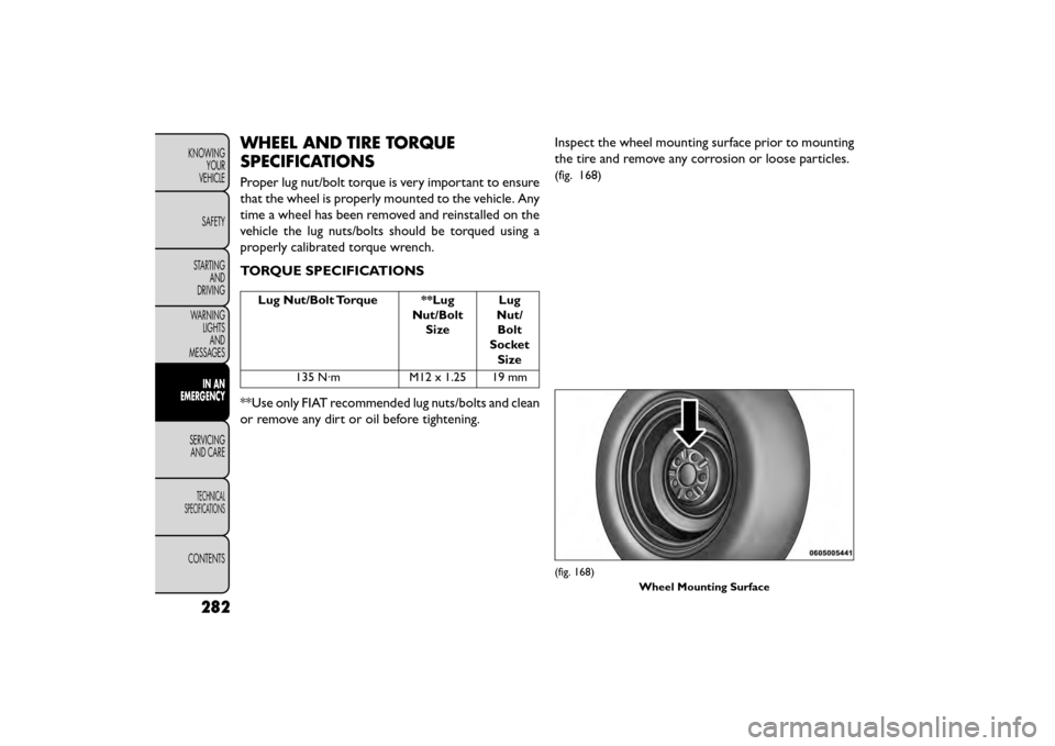
or remove any dirt or oil before tightening. Inspect the wheel mounting surface prior to mounting
the tire and remove any corrosion or loose particles.
(fig. 168)
(fig. 168)
Wheel Mounting Surface
282
KNOWINGYOUR
VEHICLE
SAFETY
STARTING AND
DRIVING
WARNING LIGHTSAND
MESSAGES
IN AN
EMERGENCY
SER VICING
AND
CARE
TECHNICAL
SPECIFICATIONS
CONTENTS
Page 302 of 412

WARNING! (Continued)
• Take care not to allow the contents of Tire
Service Kit to come in contact with hair, eyes, or
clothing. Tire Service Kit is harmful if inhaled,
swallowed, or absorbed through the skin. It
causes skin, eye, and respiratory irritation. Flush
immediately with plenty of water if there is any
contact with eyes or skin. Change clothing as
soon as possible, if there is any contact with
clothing.
• Tire Service Kit Sealant solution contains latex.
In case of an allergic reaction or rash, consult a
physician immediately. Keep Tire Service Kit out
of reach of children. If swallowed, rinse mouth
immediately with plenty of water and drink
plenty of water. Do not induce vomiting! Consult
a physician immediately.
SEALING A TIRE WITH TIRE SERVICE KIT
(A) Whenever You Stop To Use Tire Service
Kit:
1. Pull over to a safe location and turn on the vehicle’s Hazard Warning flashers.
2. Verify that the valve stem (on the wheel with the deflated tire) is in a position that is near to the
ground. This will allow the Tire Service Kit Hoses (6) and (7) to reach the valve stem and keep the Tire
Service Kit flat on the ground. This will provide the
best positioning of the kit when injecting the sealant
into the deflated tire and running the air pump.
Move the vehicle as necessary to place the valve
stem in this position before proceeding.
3. Place the transmission in PARK (auto transmission) or in Gear (manual transmission) and turn Off the
ignition.
4. Set the parking brake.
(B) Setting Up To Use Tire Service Kit:
1. Push in the Mode Select Knob (5) and turn to the Sealant Mode position.
2. Uncoil the Sealant Hose (6) and then remove the cap from the fitting at the end of the hose.
3. Place the Tire Service Kit flat on the ground next to the deflated tire.
4. Remove the cap from the valve stem and then screw the fitting at the end of the Sealant Hose (6) onto
the valve stem.
5. Uncoil the Power Plug (8) and insert the plug into the vehicle’s 12 Volt power outlet.
296
KNOWING YOUR
VEHICLE
SAFETY
STARTING AND
DRIVING
WARNING LIGHTSAND
MESSAGES
IN AN
EMERGENCY
SER VICING
AND
CARE
TECHNICAL
SPECIFICATIONS
CONTENTS
Page 305 of 412

(E) After Driving:
Pull over to a safe location. Refer to “Whenever You
Stop to Use Tire Service Kit” before continuing.
1. Turn the Mode Select Knob (5) to the Air Modeposition.
2. Uncoil the power plug and insert the plug into the vehicle's 12 Volt power outlet.
3. Uncoil the Air Pump Hose (7) (black in color) and screw the fitting at the end of hose (7) onto the
valve stem.
4. Check the pressure in the tire by reading the Pres- sure Gauge (3).
If tire pressure is less than 1.3 Bar, the tire is too
badly damaged. Do not attempt to drive the vehicle
further. Call for assistance.
If the tire pressure is 1.3 bar or higher:
1. Press the Power Button (4) to turn on Tire Service Kit and inflate the tire to the pressure indicated on
the tire and loading information label on the driver-
side door opening. NOTE:
If the tire becomes over-inflated, press the
Deflation Button to reduce the tire pressure to the
recommended inflation pressure before continuing.
2. Disconnect the Tire Service Kit from the valve stem, reinstall the cap on the valve stem and unplug
from 12 Volt outlet.
3. Place the Tire Service Kit in its proper storage area in the vehicle.
4. Have the tire inspected and repaired or replaced at the earliest opportunity at an authorized dealer or
tire service center.
5. Replace the Sealant Bottle (1) and Sealant Hose (6) assembly at your authorized dealer as soon as pos-
sible. Refer to “(F) Sealant Bottle and Hose Replace-
ment.”
NOTE: When having the tire serviced, advise the
authorized dealer or service center that the tire has
been sealed using the Tire Service Kit.
299
KNOWING
YOUR
VEHICLE
SAFETY
STARTING
AND
DRIVING
WARNING
LIGHTS
AND
MESSAGES
IN AN
EMERGENCY
SER VICING
AND
CARE
TECHNICAL
SPECIFICATIONS
CONTENTS
Page 306 of 412

(F) Sealant Bottle And Hose Replacement:
1. Uncoil the Sealant Hose (6) (clear in color).
2. Locate the round Sealant Bottle release button inthe recessed area under the sealant bottle.
3. Press the Sealant Bottle release button. The Sealant Bottle (1) will pop up. Remove the bottle and
dispose of it accordingly.
4. Clean any remaining sealant from the Tire Service Kit housing.
5. Position the new Sealant Bottle (1) in the housing so that the Sealant Hose (6) aligns with the hose slot in
the front of the housing. Press the bottle into the
housing. An audible click will be heard indicating the
bottle is locked into place.
6. Verify that the cap is installed on the fitting at the end of the Sealant Hose (6) and return the hose to
its storage area (located on the bottom of the air
pump).
7. Return the Tire Service Kit to its storage location in the vehicle.REPLACEMENT BULBS
All the inside bulbs are brass or glass wedge base.
Aluminum base bulbs are not approved and should not
be used for replacement.
LIGHT BULBS – Interior Bulb Number
Courtesy/Reading Lamps (Incandescent).......578
Courtesy/Reading Lamps (Optional LED) ......LED
(Serviced at Authorized Dealer)
Glove Box Lamp ........................194
Cargo Lamp ...........................579
Optional Door Map Pocket/Cupholder .......LED
(Serviced at Authorized Dealer)
NOTE: For lighted switches, see your authorized
dealer for replacement instructions.
300
KNOWING YOUR
VEHICLE
SAFETY
STARTING AND
DRIVING
WARNING LIGHTSAND
MESSAGES
IN AN
EMERGENCY
SER VICING
AND
CARE
TECHNICAL
SPECIFICATIONS
CONTENTS
Page 308 of 412

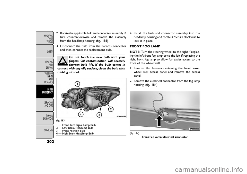
2.Rotate the applicable bulb and connector assembly ¼
turn counterclockwise and remove the assembly
from the headlamp housing.
(fig. 183)
3. Disconnect the bulb from the harness connector and then connect the replacement bulb.
Do not touch the new bulb with your
fingers. Oil contamination will severely
shorten bulb life. If the bulb comes in
contact with any oily surface, clean the bulb with
rubbing alcohol. 4. Install the bulb and connector assembly into the
headlamp housing and rotate it ¼ turn clockwise to
lock it in place.
FRONT FOG LAMP
NOTE: Turn the steering wheel to the right if replac-
ing the left front fog lamp or to the left if replacing the
right front fog lamp to allow for easier access to the
front of the wheel well.
1. Remove the fasteners retaining the front lower wheel well access panel and remove the access
panel.
2. Remove the electrical connector from the fog lamp housing. (fig. 184)
(fig. 183)
1 — Front Turn Signal Lamp Bulb
2 — Low Beam Headlamp Bulb
3 — Front Position Bulb
4 — High Beam Headlamp Bulb
(fig. 184)
Front Fog Lamp Electrical Connector
302
KNOWINGYOUR
VEHICLE
SAFETY
STARTING AND
DRIVING
WARNING LIGHTSAND
MESSAGES
IN AN
EMERGENCY
SER VICING
AND
CARE
TECHNICAL
SPECIFICATIONS
CONTENTS