Page 120 of 412

•Do not exceed the maximum power of
160Watts (13 Amps) at 12Volts. If the 160
Watt (13 Amp) power rating is exceeded
the fuse protecting the system will need to be
replaced.
• The power outlet on the bottom of the center
console shares the fuse with the power outlet on
the back of the console.The combined usage must
not exceed 160 Watts (13 Amps) at 12 Volts.
• Power outlets are designed for accessory plugs
only. Do not insert any other object in the power
outlets as this will damage the outlet and blow
the fuse. Improper use of the power outlet can
cause damage not covered by your New Vehicle
Limited Warranty.
(fig. 86)WARNING!
To avoid serious injury or death:
•
Only devices designed for use in this type
of outlet should be inserted into any 12 Volt outlet .
• Do not touch with wet hands.
• Close the lid when not in use and while driving
the vehicle.
• If this outlet is mishandled, it may cause an
electric shock and failure.
(fig. 86)
Power Outlet Fuses
1 — F103 20 A Yellow Power Outlet Console Bin & Power
Outlet Console Rear
2 — F102 20 A Yellow Cigar Lighter Instrument Panel &
Power Outlet Left Rear Cargo Area
114
KNOWINGYOUR
VEHICLE
SAFETY
STAR
TINGAND
DRIVING
WARNING LIGHTSAND
MESSAGES
IN AN
EMERGENCY
SERVICINGAND CARE
TECHNICAL
SPECIFICATIONS
CONTENTS
Page 313 of 412

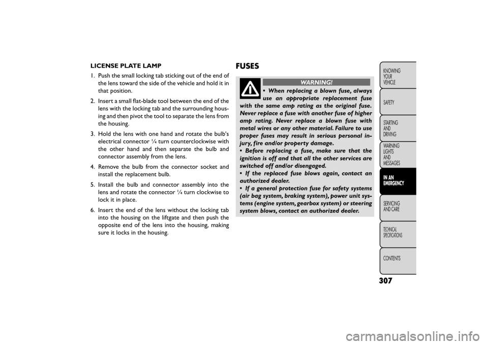
LICENSE PLATE LAMP
1. Push the small locking tab sticking out of the end ofthe lens toward the side of the vehicle and hold it in
that position.
2. Insert a small flat-blade tool between the end of the lens with the locking tab and the surrounding hous-
ing and then pivot the tool to separate the lens from
the housing.
3. Hold the lens with one hand and rotate the bulb's electrical connector ¼ turn counterclockwise with
the other hand and then separate the bulb and
connector assembly from the lens.
4. Remove the bulb from the connector socket and install the replacement bulb.
5. Install the bulb and connector assembly into the lens and rotate the connector ¼ turn clockwise to
lock it in place.
6. Insert the end of the lens without the locking tab into the housing on the liftgate and then push the
opposite end of the lens into the housing, making
sure it locks in the housing.FUSES
WARNING!
• When replacing a blown fuse, always
use an
appropriate replacement fuse
with the same amp rating as the original fuse.
Never replace a fuse with another fuse of higher
amp rating. Never replace a blown fuse with
metal wires or any other material. Failure to use
proper fuses may result in serious personal in-
jury, fire and/or property damage.
• Before replacing a fuse, make sure that the
ignition is off and that all the other services are
switched off and/or disengaged.
• If the replaced fuse blows again, contact an
authorized dealer.
• If a general protection fuse for safety systems
(air bag system, braking system), power unit sys-
tems (engine system, gearbox system) or steering
system blows, contact an authorized dealer.
307
KNOWING
YOUR
VEHICLE
SAFETY
STARTING
AND
DRIVING
WARNING
LIGHTS
AND
MESSAGES
IN AN
EMERGENCY
SER VICING
AND
CARE
TECHNICAL
SPECIFICATIONS
CONTENTS
Page 314 of 412

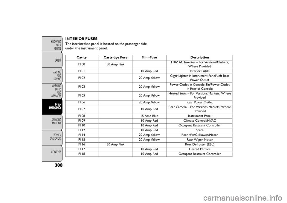
INTERIOR FUSES
The interior fuse panel is located on the passenger side
under the instrument panel.
CavityCartridge Fuse Mini-Fuse Description
F100 30 Amp Pink 110V AC Inverter – For Versions/Markets,
Where Provided
F101 10 Amp RedInterior Lights
F102 20 Amp YellowCigar Lighter in Instrument Panel/Left Rear
Power Outlet
F103 20 Amp YellowPower Outlet in Console Bin/Power Outlet
in Rear of Console
F105 20 Amp YellowHeated Seats – For Versions/Markets, Where
Provided
F106 20 Amp YellowRear Power Outlet
F107 10 Amp RedRear Camera – For Versions/Markets, Where
Provided
F108 15 Amp BlueInstrument Panel
F109 10 Amp RedClimate Control/HVAC
F110 10 Amp RedOccupant Restraint Controller
F112 10 Amp RedSpare
F114 20 Amp YellowRear HVAC Blower/Motor
F115 20 Amp YellowRear Wiper Motor
F116 30 Amp Pink Rear Defroster (EBL)
F117 10 Amp RedHeated Mirrors
F118 10 Amp RedOccupant Restraint Controller
308
KNOWING
YOUR
VEHICLE
SAFETY
STARTING AND
DRIVING
WARNING LIGHTSAND
MESSAGES
IN AN
EMERGENCY
SER VICING
AND
CARE
TECHNICAL
SPECIFICATIONS
CONTENTS
Page 316 of 412
UNDERHOOD FUSES (POWER
DISTRIBUTION CENTER)
The power distribution center is located in the engine
compartment.
(fig. 191)
Cavity Cartridge Fuse Mini-FuseDescription
F101 60 Amp Yellow Interior Power Distribution Center Rail
F102 60 Amp Yellow Interior Power Distribution Center Rail
F103 60 Amp Yellow Interior Power Distribution Center Rail
F105 60 Amp Yellow Interior Power Distribution Center Rail
Ignition Run Relay
F106 60 Amp Yellow Interior Power Distribution Center Rail Run/
Accessory Relays
F139 40 Amp Green Climate Control System Blower
F140 30 Amp Pink Power Locks
F141 40 Amp Green Anti-Lock Brake System
F142 40 Amp Green Glow Plugs – For Versions/Markets, Where
Provided
F143 40 Amp Green Exterior Lights 1
(fig. 191)
Power Distribution Center (Fuses)
310
KNOWINGYOUR
VEHICLE
SAFETY
STARTING AND
DRIVING
WARNING LIGHTSAND
MESSAGES
IN AN
EMERGENCY
SER VICING
AND
CARE
TECHNICAL
SPECIFICATIONS
CONTENTS
Page 338 of 412
ENGINE COMPARTMENT — 2.4L
(fig. 197)
(fig. 197)
1 — Engine Coolant Reservoir7 — Power Distribution Center (Fuses)
2 — Power Steering Fluid Reservoir 8 — Air Cleaner Filter
3 — Engine Oil Fill 9 — Automatic Transmission Dipstick (4–Speed Only)
4 — Brake Fluid Reservoir 10 — Washer Fluid Reservoir
5 — Remote Jump Start (Positive Battery Post) 11 — Coolant Reservoir Cap
6 — Remote Jump Start (Negative Battery Post) 12 — Engine Oil Dipstick
332
KNOWING
YOUR
VEHICLE
SAFETY
STARTING AND
DRIVING
WARNING LIGHTSAND
MESSAGES
IN AN
EMERGENCY
SERVICINGAND C ARE
TECHNICAL
SPECIFICATIONS
CONTENTS
Page 339 of 412
ENGINE COMPARTMENT — 3.6L
(fig. 198)
(fig. 198)
1 — Engine Coolant Reservoir5 — Air Cleaner Filter
2 — Power Steering Fluid Reservoir 6 — Washer Fluid Reservoir
3 — Brake Fluid Reservoir 7 — Engine Oil Dipstick
4 — Power Distribution Center (Fuses) 8 — Engine Oil Fill
333
KNOWING
YOUR
VEHICLE
SAFETY
STARTING
AND
DRIVING
WARNING
LIGHTS
AND
MESSAGES
IN AN
EMERGENCY
SERVICING
AND CARE
TECHNICAL
SPECIFICATIONS
CONTENTS
Page 340 of 412
ENGINE COMPARTMENT — 2.0L DIESEL
(fig. 199)
(fig. 199)
1 — Engine Coolant Reservoir5 — Brake Fluid Reservoir
2 — Power Steering Fluid Reservoir 6 — Power Distribution Center (Fuses)
3 — Engine Oil Fill 7 — Air Cleaner Filter
4 — Engine Oil Dipstick 8 — Washer Fluid Reservoir
334
KNOWING
YOUR
VEHICLE
SAFETY
STARTING AND
DRIVING
WARNING LIGHTSAND
MESSAGES
IN AN
EMERGENCY
SERVICINGAND C ARE
TECHNICAL
SPECIFICATIONS
CONTENTS
Page 401 of 412

Requirements......................... .379
Saver Mode ............................29
Specifications . . . . . .................... .385
Tank Capacity . . . . . . . . . . . ...............384
Fuel, Flexible . . . . . . . . . . . . . ................381
Fueling . . . . . . . . ........................ .190
Fuel Optimizer ............................29
Fuel Saver ................................29
Fuel System Caution . ...................... .191
Fuses . ................................ .307
Gas Cap (Fuel Filler Cap) .................... .190
Gas Gauge (Fuel Gauge) .......................7
Gasoline, Clean Air ....................... .380
Gasoline (Fuel) .......................... .379
Conserving ............................29
Gauges Coolant Temperature . .....................8
Fuel . . ................................7
Speedometer ............................7
Tachometer .............................7
Gear Ranges . . . . . . . . . . . . . . . . . ............249
Gear Select Lever Override . . . . . . . ............313
General Information . . . . . . . . . . . . . ........12, 158
General Maintenance ...................... .335
Glass Cleaning . . ......................... .358
Gross Axle Weight Rating . . . . . . . .............259
Gross Vehicle Weight Rating . . . . . . . ...........258
Hazard Driving Through Flowing, Rising, or Shallow Standing
Water .............................. .257
Hazard Warning Flasher . ................... .107Headlights
Automatic .............................92
Bulb Replacement ...................... .301
Cleaning ............................ .357
Delay ................................93
High Beam ........................... .301
High Beam/Low Beam Select Switch ............95
Leveling ...............................92
Lights On Reminder ......................94
On With Wipers .................... .93, 100
Passing ...............................95
Switch ................................92
Time Dela y............................
93
Washers ............................ .100
Headlight Washers ........................ .100
Head Restraints ............................54
Heated Mirrors ............................69
Heated Seats ..............................50
High Beam Indicator ....................... .274
High Beam/Low Beam Select (Dimmer) Switch .......95
Hill Start Assist .......................... .147
Holder, Coin ............................ .108
Holder, Cup ............................ .115
Hood Release ........................... .136
Ignition Key ..................................8
Illuminated Entry ...........................97
Immobilizer (Sentry Key) ......................11
Inflation Pressure Tires ..................... .275
Information Center, Vehicle ....................20
Inside Rearview Mirror .......................66
Instrument Cluster ........................ .273
395
KNOWING
YOUR
VEHICLE
SAFETY
STARTING
AND
DRIVING
WARNING
LIGHTS
AND
MESSAGES
IN AN
EMERGENCY
SERVICING
AND CARE
TECHNICAL
SPECIFICATIONS
CONTENTS