2015 FIAT 500X wheel
[x] Cancel search: wheelPage 123 of 240
IN AN EMERGENCY
A punctured tyre or a burnt-out bulb?
At times, a problem may interfere
with our journey.
The pages on emergencies can help
you to deal with critical situations
independently and with calm.
In an emergency we recommend that
you call the freephone number found in
the Warranty Booklet.
It is also possible to call the national or
international universal freephone
number to search for the nearest Fiat
Dealership.HAZARD WARNING LIGHTS...........122
BULB REPLACEMENT....................122
REPLACING FUSES........................128
CHANGING A WHEEL ....................133
FIX&GO AUTOMATIC KIT ................136
EMERGENCY STARTING ................138
FUEL CUT-OFF SYSTEM ................140
AUTOMATIC TRANSMISSION
GEAR LEVER UNLOCKING.............140
TOWING THE VEHICLE ..................142
121
15-12-2014 8:23 Pagina 121
Page 127 of 240
REPLACING AN
EXTERNAL BULB
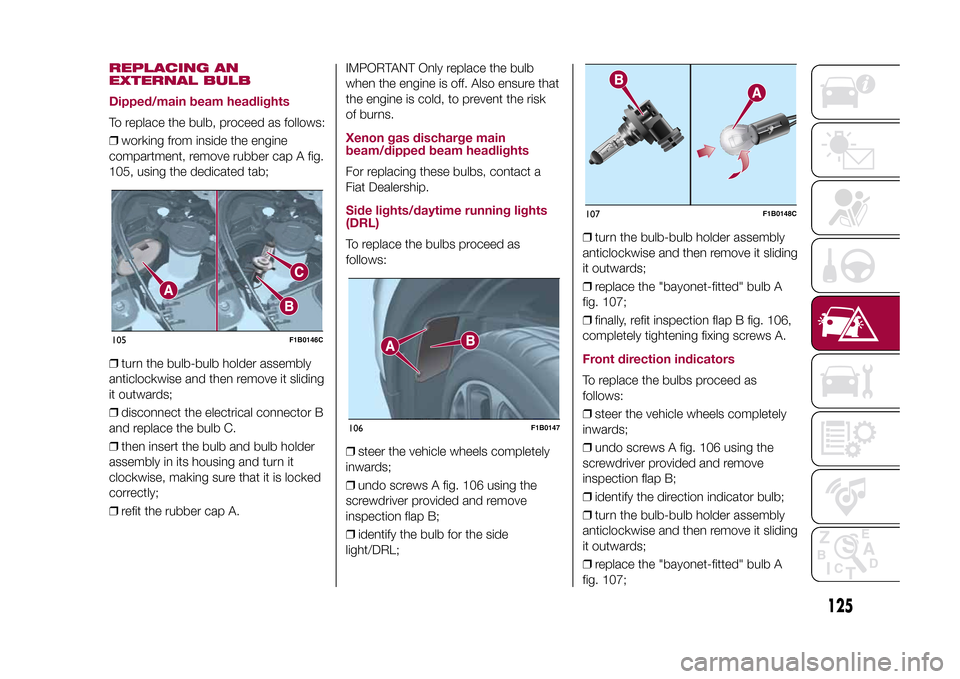
Dipped/main beam headlightsTo replace the bulb, proceed as follows:
❒working from inside the engine
compartment, remove rubber cap A fig.
105, using the dedicated tab;
❒turn the bulb-bulb holder assembly
anticlockwise and then remove it sliding
it outwards;
❒disconnect the electrical connector B
and replace the bulb C.
❒then insert the bulb and bulb holder
assembly in its housing and turn it
clockwise, making sure that it is locked
correctly;
❒refit the rubber cap A.IMPORTANT Only replace the bulb
when the engine is off. Also ensure that
the engine is cold, to prevent the risk
of burns.
Xenon gas discharge main
beam/dipped beam headlightsFor replacing these bulbs, contact a
Fiat Dealership.Side lights/daytime running lights
(DRL)To replace the bulbs proceed as
follows:
❒steer the vehicle wheels completely
inwards;
❒undo screws A fig. 106 using the
screwdriver provided and remove
inspection flap B;
❒identify the bulb for the side
light/DRL;❒turn the bulb-bulb holder assembly
anticlockwise and then remove it sliding
it outwards;
❒replace the "bayonet-fitted" bulb A
fig. 107;
❒finally, refit inspection flap B fig. 106,
completely tightening fixing screws A.
Front direction indicatorsTo replace the bulbs proceed as
follows:
❒steer the vehicle wheels completely
inwards;
❒undo screws A fig. 106 using the
screwdriver provided and remove
inspection flap B;
❒identify the direction indicator bulb;
❒turn the bulb-bulb holder assembly
anticlockwise and then remove it sliding
it outwards;
❒replace the "bayonet-fitted" bulb A
fig. 107;
105
F1B0146C
106
F1B0147
107
F1B0148C
125
15-12-2014 8:23 Pagina 125
Page 128 of 240
❒finally, refit inspection flap B fig. 106,
completely tightening fixing screws A.Fog lightsTo replace the bulbs proceed as
follows:
❒steer the vehicle wheels completely
inwards;
❒undo screws A fig. 106 using the
screwdriver provided and remove
inspection flap B;
❒identify the fog light bulb;
❒turn the bulb-bulb holder assembly
anticlockwise and then remove it sliding
it outwards;
❒disconnect the electrical connector;
❒replace the bulb-bulb holder
assembly B fig. 107.
❒reconnect the electrical connector to
the new bulb-bulb holder assembly,
then fit it ensuring that it locks correctly;
❒fit the assembly turning it clockwise,
ensuring that it locks correctly;
❒finally, refit inspection flap B fig. 106,
completely tightening fixing screws A.Side direction indicatorsIMPORTANT The procedure is only
described by way of illustration. It
is advisable to contact a Fiat Dealership
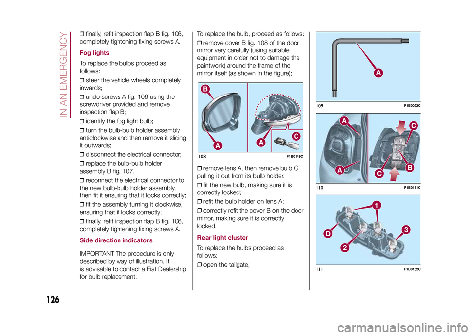
for bulb replacement.To replace the bulb, proceed as follows:
❒remove cover B fig. 108 of the door
mirror very carefully (using suitable
equipment in order not to damage the
paintwork) around the frame of the
mirror itself (as shown in the figure);
❒remove lens A, then remove bulb C
pulling it out from its bulb holder.
❒fit the new bulb, making sure it is
correctly locked;
❒refit the bulb holder on lens A;
❒correctly refit the cover B on the door
mirror, making sure it is correctly
locked.
Rear light clusterTo replace the bulbs proceed as
follows:
❒open the tailgate;108
F1B0149C
109
F1B0022C
110
F1B0151C
111
F1B0152C
126
IN AN EMERGENCY
15-12-2014 8:23 Pagina 126
Page 135 of 240
CHANGING A WHEELJACKPlease note that:
❒the weight of the jack is 2.8 kg;
❒The jack requires no adjustment;
❒the jack cannot be repaired and in
the event of a fault it must be replaced
by another original one;
❒No tool other than its cranking device
may be fitted on the jack.CHANGING PROCEDURE
132) 133) 134) 135) 136) 137) 138) 139)
Proceed as follows:
❒stop the vehicle in a position that is
not dangerous for oncoming traffic
where you can change the wheel safely.
The ground should be flat if possible,
and sufficiently firm;
❒stop the engine, engage the hazard
warning lights and the electric parking
brake;
❒engage first gear or reverse or, for
versions with automatic transmission,
move the lever to position P (Park);
❒wear the reflective safety jacket
(compulsory by law in certain countries)
before getting out of the vehicle;❒open the boot and position the
reconfigurable load platform in
an inclined position (see "Boot" in the
"Knowing your vehicle" chapter);
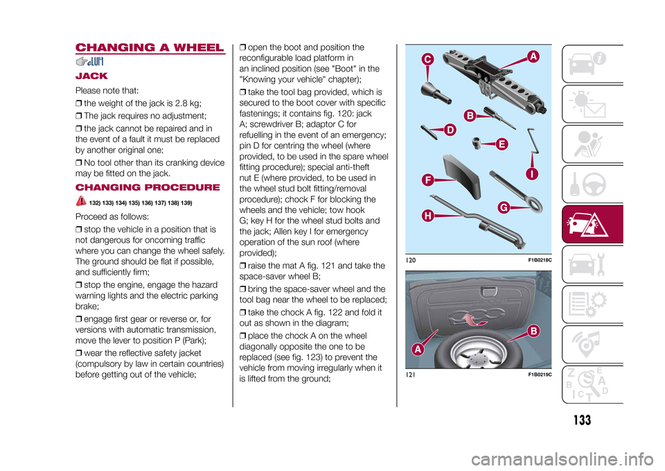
❒take the tool bag provided, which is
secured to the boot cover with specific
fastenings; it contains fig. 120: jack
A; screwdriver B; adaptor C for
refuelling in the event of an emergency;
pin D for centring the wheel (where
provided, to be used in the spare wheel
fitting procedure); special anti-theft
nut E (where provided, to be used in
the wheel stud bolt fitting/removal
procedure); chock F for blocking the
wheels and the vehicle; tow hook
G; key H for the wheel stud bolts and
the jack; Allen key I for emergency
operation of the sun roof (where
provided);
❒raise the mat A fig. 121 and take the
space-saver wheel B;
❒bring the space-saver wheel and the
tool bag near the wheel to be replaced;
❒take the chock A fig. 122 and fold it
out as shown in the diagram;
❒place the chock A on the wheel
diagonally opposite the one to be
replaced (see fig. 123) to prevent the
vehicle from moving irregularly when it
is lifted from the ground;
120
F1B0218C
121
F1B0219C
133
15-12-2014 8:23 Pagina 133
Page 136 of 240
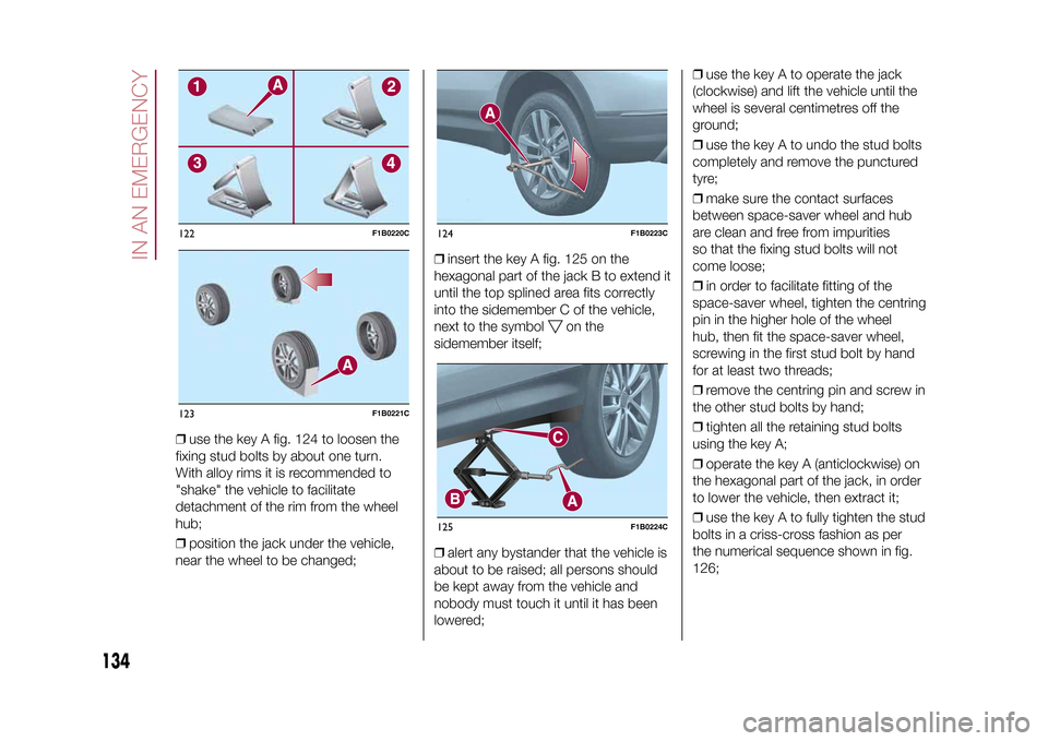
❒use the key A fig. 124 to loosen the
fixing stud bolts by about one turn.
With alloy rims it is recommended to
"shake" the vehicle to facilitate
detachment of the rim from the wheel
hub;
❒position the jack under the vehicle,
near the wheel to be changed;❒insert the key A fig. 125 on the
hexagonal part of the jack B to extend it
until the top splined area fits correctly
into the sidemember C of the vehicle,
next to the symbol
on the
sidemember itself;
❒alert any bystander that the vehicle is
about to be raised; all persons should
be kept away from the vehicle and
nobody must touch it until it has been
lowered;❒use the key A to operate the jack
(clockwise) and lift the vehicle until the
wheel is several centimetres off the
ground;
❒use the key A to undo the stud bolts
completely and remove the punctured
tyre;
❒make sure the contact surfaces
between space-saver wheel and hub
are clean and free from impurities
so that the fixing stud bolts will not
come loose;
❒in order to facilitate fitting of the
space-saver wheel, tighten the centring
pin in the higher hole of the wheel
hub, then fit the space-saver wheel,
screwing in the first stud bolt by hand
for at least two threads;
❒remove the centring pin and screw in
the other stud bolts by hand;
❒tighten all the retaining stud bolts
using the key A;
❒operate the key A (anticlockwise) on
the hexagonal part of the jack, in order
to lower the vehicle, then extract it;
❒use the key A to fully tighten the stud
bolts in a criss-cross fashion as per
the numerical sequence shown in fig.
126;
122
F1B0220C
123
F1B0221C
124
F1B0223C
125
F1B0224C
134
IN AN EMERGENCY
15-12-2014 8:23 Pagina 134
Page 137 of 240

❒place the punctured tyre in the boot
upside down (with the outer part facing
upwards), then reposition the jack
and the used tools;
❒reposition the boot mat then
reposition the reconfigurable load
platform in a flat position (see "Boot" in
the "Knowing your vehicle" chapter).
Restore the standard wheel as soon as
possible, because, once placed in the
associated compartment, the boot load
platform is rendered uneven as the
standard wheel is larger than the
space-saver wheel.
WARNING
132)If left in the passenger compartment,
the punctured wheel and jack constitute
a serious risk to the safety of occupants in
the event of accidents or sharp braking.
Therefore, always place both the jack and
punctured wheel in the dedicated housing
in the boot.
133)It is extremely dangerous to attempt
to change a wheel on the side of the
vehicle next to the driving lane: make sure
that the vehicle is at a sufficient distance
from the road, to avoid being run over.
134)Alert other drivers that the vehicle is
stationary in compliance with local
regulations: hazard warning lights, warning
triangle, etc. Any passengers on board
should leave the vehicle, especially if it is
heavily laden. Passengers should stay
away from on-coming traffic while the
wheel is being changed. For safety
reasons, always block the wheels with the
chocks provided.135)The vehicle's driving characteristics
will be modified with the space-saver wheel
fitted. Avoid violent acceleration and
braking, abrupt steering and fast cornering.
The overall duration of the space-saver
wheel is about 3000 km, after which the
relevant tyre must be replaced with another
one of the same type. Never install a
standard tyre on a rim that is designed for
use with a space-saver wheel. Have the
wheel repaired and refitted as soon as
possible. Using two or more space-saver
wheels at the same time is forbidden.
Do not grease the threads of the stud bolts
before fitting them: they might slip out
when driving!
136)The space-saver wheel is specific to
your vehicle: do not use it on other models,
or use the space-saver wheel of other
models on your vehicle. The space-saver
wheel must only be used in the event of an
emergency. It must only be used for the
distance necessary to reach a service point
and the vehicle speed must not exceed
80 km/h. The space-saver wheel has
an orange label that summarises the main
cautions for use and limitations. Never
remove or cover the sticker.
126
F1B0225C
135
15-12-2014 8:23 Pagina 135
Page 138 of 240
137)The jack is a tool developed and
designed only for changing a wheel, if a
tyre gets punctured or damaged, on the
vehicle with which it is supplied or on other
vehicles of the same model. It must not
be used, for example, to jack other vehicle
models or objects. Never use the jack to
carry out maintenance or repairs under the
vehicle. Never position yourself under a
jacked vehicle. Should it be necessary to
work under the vehicle, contact a Fiat
Dealership. Incorrectly positioning the jack
may cause the vehicle to fall: use it only
in the positions indicated. Do not use the
jack for loads higher than the one shown
on its label.
138)The space-saver wheel cannot be
fitted with snow chains. If a front (drive) tyre
is punctured and chains are needed, use
a standard wheel from the rear axle and
install the space-saver wheel on the rear
axle. In this way, with two normal drive
wheels at the front axle, it is possible to use
snow chains (this instruction is also valid
for 4x4 versions).
139)Never tamper with the inflation valve.
Never introduce tools of any kind between
the rim and the tyre. Check tyre and
space-saver wheel pressures regularly,
complying with the values given in the
"Technical specifications" chapter.
FIX&GO AUTOMATIC
KIT(where provided)DESCRIPTION
140) 141) 142) 143) 144) 145) 146) 147)54)3)
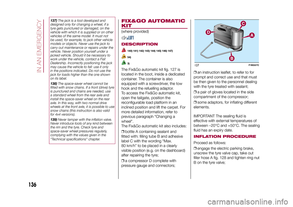
The Fix&Go automatic kit fig. 127 is
located in the boot, inside a dedicated
container. The container is also
equipped with a screwdriver, the tow
hook and the refuelling adaptor.
To access the Fix&Go automatic kit,
open the tailgate, position the
reconfigurable load platform in an
inclined position and lift the carpet. For
more detailed information, refer to
previous paragraph "Changing a
wheel".
The Fix&Go automatic kit also includes:
❒bottle A containing sealant and
fitted with: filling tube B and adhesive
label C with the wording “Max.
80 km/h” to be placed in a clearly
visible position (e.g. on the dashboard)
after repairing the tyre;
❒a compressor D complete with
pressure gauge and connectors;❒an instruction leaflet, to refer to for
prompt and correct use and that must
be then given to the personnel dealing
with the tyre treated with sealant;
❒a pair of gloves located in the side
compartment of the compressor;
❒some adaptors, for inflating different
elements.
IMPORTANT The sealing fluid is
effective with external temperatures of
between –20°C and +50°C. The sealing
fluid has an expiry date.
INFLATION PROCEDUREProceed as follows:
❒engage the electric parking brake,
unscrew the tyre valve cap, take out
filler hose A fig. 128 and tighten ring nut
B on the tyre valve;127
F1B0227C
136
IN AN EMERGENCY
15-12-2014 8:23 Pagina 136
Page 139 of 240

❒make sure that the switch for the
compressor is in position0(off), start
the engine, insert the plug into the
power socket located on the central
tunnel and switch on the compressor
by bringing the switch to positionI(on);
❒inflate the tyre to the pressure
indicated in the “Wheels” paragraph
(see “Technical data” chapter). In order
to obtain a more precise reading, check
the pressure value on pressure gauge
B with the compressor off;
❒if after five minutes pressure is not at
least 1.8 bar, disengage the
compressor from the valve and power
socket, then move the vehicle forwards
by approx. ten metres in order to
distribute the sealing fluid inside the tyre
evenly, then repeat the inflation
operation;❒if after this operation you still cannot
reach at least 1.8 bar after 5 minutes
from switching on the compressor,
do not resume driving but contact a
Fiat Dealership;
❒after having driven for about 10
minutes, stop and re-check the tyre
pressure; remember to engage the
electric parking brake;
❒if a pressure value of at least 1.8 bar
is detected, restore the correct
pressure (with engine running and
electric parking brake engaged),
resume driving immediately and drive
with great care to a Fiat Dealership.
WARNING
140)Punctures on the sides of the tyre
may not be repaired. Do not use the
Fix&Go automatic kit if the tyre is damaged
due to travelling when flat.
141)Wear the protective gloves provided
with the Fix&Go automatic kit.
142)Apply the adhesive label where it can
be easily seen by the driver as a reminder
that the tyre has been treated with the
Fix&Go automatic kit. Drive carefully,
particularly on bends. Do not exceed 80
km/h. Do not accelerate or brake suddenly.
143)If the pressure has fallen below 1.8
bar, do not drive any further: the Fix&Go
automatic kit cannot guarantee proper hold
because the tyre is too damaged. Contact
a Fiat Dealership.144)You must always indicate that the tyre
was repaired using the Fix&Go automatic
kit. Give the leaflet to the technicians who
will be handling the tyre that was treated
using the Fix&Go automatic kit.
145)Repair is not possible if the wheel rim
is damaged (tread is deformed, causing
air to escape). Do not remove foreign
bodies (screws or nails) from the tyre.
146)Do not operate the compressor for
longer than 20 minutes consecutively. Risk
of overheating. The Fix&Go automatic kit
is not suitable for definitive repairs, so
the repaired tyres may only be used
temporarily.
147)The bottle contains ethylene glycol
and latex: it may cause an allergic reaction.
It is harmful if swallowed. It is irritant for
the eyes. It may cause sensitisation if
inhaled or on contact. Avoid contact with
eyes, skin and clothes. In the case of
contact, wash immediately with plenty of
water. In the event that it is swallowed, do
not induce vomiting. Rinse out your mouth,
drink large quantities of water and seek
immediate medical attention. Keep out of
the reach of children. The product must
not be used by asthmatics. Do not inhale
the vapours during insertion and suction.
Call a doctor immediately if allergic
reactions are noted. Store the bottle in its
proper compartment, away from sources
of heat. The sealant has an expiry date.
Replace the cylinder containing the sealant
after the expiry date.
128
F1B0229C
137
15-12-2014 8:23 Pagina 137