2015 FIAT 500X key
[x] Cancel search: keyPage 105 of 240
❒"Drive Away Release": the electric
parking brake will automatically
disengage with the driver side seat belt
fastened and the detection of an action
performed by the driver to move the
vehicle (forward gear or reverse gear);
❒"Safe Hold": if the vehicle speed
is lower than 3 km/h and, for the
versions with automatic transmission,
the gear lever is not in P (Park) position
and the driver intention of leaving the
vehicle is detected, the electric parking
brake will automatically engage to
hold the vehicle in safety conditions;
❒"Auto Apply": if the vehicle speed is
lower than 3 km/h, the electric parking
brake will automatically engage with the
gear lever moved to P (Park) position
(versions with automatic transmission),
or with the ignition device at STOP
(versions with manual gearbox). The
LED on the switch turns on together
with the
warning light on the
instrument panel when the parking
brake is engaged and applied to the
wheels. Each automatic parking brake
engagement can be cancelled by
pressing the switch on the central
tunnel and at the same time moving the
gear lever for the automatic
transmission to position P (Park) or the
ignition device to STOP (versions with
manual gearbox).
SAFE HOLDIt is a safety function that automatically
engages
the electric parking brake in
the event of a dangerous condition for
the vehicle.
If:
❒the vehicle speed is below 3 km/h;
❒the gear lever is not at P (Park)
(versions with automatic transmission);
❒the driver's seat belt is not fastened;
❒the driver side door is open;
❒no attempted operation of the brake
pedal or, on versions with manual
gearbox, the clutch pedal or the
accelerator pedal is detected;
the electric parking brake engages
automatically to prevent vehicle
movement.
The Safe Hold function can be
temporarily disabled by pressing the
switch located on the central tunnel
and the brake pedal at the same time,
with the vehicle stationary and the
driver side door open.
Once disabled, the function will activate
again when the vehicle speed reaches
20 km/h or the ignition device is moved
to STOP and then to MAR.
WARNING
107)In the case of parking manoeuvres on
roads on a gradient, steer the wheels,
engage the parking brake, the first gear if
uphill and the reverse if downhill; on
versions with automatic transmission, set
the lever to "P". If the vehicle is parked
on a steep slope, you need to block the
wheels with a wedge or stone.
108)Never leave children unattended in
the vehicle. Always remove the key when
leaving the vehicle and take it with you.
109)The electric parking brake must
always be engaged when leaving
the vehicle.
103
12-1-2015 15:6 Pagina 103
Page 108 of 240
IGNITION LOCK AND
PARK POSITIONVersions equipped with the Keyless
Go system: this function requires the
gear lever to be positioned at P (Park);
then bring the ignition device to STOP.
Versions equipped with key without
remote control: this function requires
the gear lever to be positioned at P
(Park) before extracting the key from
the ignition device.
If the vehicle battery is flat and the
ignition key is engaged, the latter is
locked in position.
To remove the key manually see
paragraph "Automatic transmission
lever unlock" in chapter "In an
emergency".GEAR ENGAGEMENT
DISABLING WITHOUT
BRAKE PEDAL PRESSEDThis system prevents you from moving
the gear lever from position P (Park) if
the brake pedal has not been previously
depressed.To bring the gear lever to a position
other than P (Park), the ignition device
must be in position MAR (engine on
or off) and the brake pedal must be
depressed. Button A fig. 91 on the gear
lever knob must also be pressed.
STEERING WHEEL
CONTROLS(where provided)
On some versions, the gearbox can be
managed sequentially using the
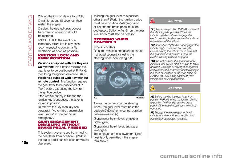
steering wheel controls fig. 92.
To use the controls on the steering
wheel, the gear lever must be in the
position D (Drive) or in central position
between (+) and (–):
❒operating the (+) lever: engage a
higher gear;
❒operating the (–) lever: engage a
lower gear.
The engagement of a lower (or higher)
gear is only permitted if the engine
rpm allow it.
WARNING
111)Never use position P (Park) instead of
the electric parking brake. When the
vehicle is parked, always engage the
electric parking brake to prevent accidental
movements of the vehicle.
112)If position P (Park) is not engaged the
vehicle might move and hurt people.
Before leaving the vehicle make sure that
the gear lever is in position P and the
electric parking brake is engaged.
113)Do not position the gear lever at N
(Neutral), nor switch off the engine to travel
downhill. This type of driving is dangerous
and reduces the possibility of intervening in
the case of variation of the road traffic or
surface. You risk losing control of your
vehicle and causing accidents.
WARNING
38)Before moving the gear lever from
position P (Park), bring the ignition device
to position MAR and press the brake
pedal. Otherwise the gear lever might be
damaged.
39)Engage the reverse gear only with
vehicle at a standstill, engine idling and
accelerator completely released.
92
F1B0508C
106
STARTING AND DRIVING
15-12-2014 8:23 Pagina 106
IMPORTANT In the event of a
temporary failure it is in any case
recommended to contact a Fiat
Dealership as soon as possible.❒bring the ignition device to STOP;
❒wait for about 10 seconds, then
restart the engine;
❒select the desired gear: correct
transmission operation should
be restored.
Page 134 of 240

BOOT FUSE BOXNOTE The configuration of the boot may vary in accordance with the equipment on the vehicle.Fuse box BUSERSFUSE AMPEREHI-FI system F2 20
Electric sun roof F3 20
Front seat electric lumbar adjustment (driver guide) F4 7.5
Electric front seat adjustment (driver side) F5 30
Electric front seat adjustment (driver side and passenger side) F6 7.5
Electric front seat lumbar adjustment (driver side and passenger
side)F7 30
WARNING
128)If the fuse blows again contact a Fiat Dealership.
129)Never replace a fuse with another with a higher amp rating; DANGER OF FIRE
130)If a fuse NOT described on this page and on the previous one blows, contact a Fiat Dealership.
131)Before replacing a fuse, make sure that the ignition device has been taken to STOP, that the ignition key, if mechanical, has been
removed and that all the other devices are switched off and/or deactivated.
WARNING
52)Never replace a blown fuse with metal wires or other material.
53)If it is necessary to wash the engine compartment, take care not to directly hit the fuse box and the window wiper motor with the water
jet.
132
IN AN EMERGENCY
15-12-2014 8:23 Pagina 132
Page 135 of 240
CHANGING A WHEELJACKPlease note that:
❒the weight of the jack is 2.8 kg;
❒The jack requires no adjustment;
❒the jack cannot be repaired and in
the event of a fault it must be replaced
by another original one;
❒No tool other than its cranking device
may be fitted on the jack.CHANGING PROCEDURE
132) 133) 134) 135) 136) 137) 138) 139)
Proceed as follows:
❒stop the vehicle in a position that is
not dangerous for oncoming traffic
where you can change the wheel safely.
The ground should be flat if possible,
and sufficiently firm;
❒stop the engine, engage the hazard
warning lights and the electric parking
brake;
❒engage first gear or reverse or, for
versions with automatic transmission,
move the lever to position P (Park);
❒wear the reflective safety jacket
(compulsory by law in certain countries)
before getting out of the vehicle;❒open the boot and position the
reconfigurable load platform in
an inclined position (see "Boot" in the
"Knowing your vehicle" chapter);
❒take the tool bag provided, which is
secured to the boot cover with specific
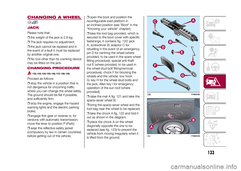
fastenings; it contains fig. 120: jack
A; screwdriver B; adaptor C for
refuelling in the event of an emergency;
pin D for centring the wheel (where
provided, to be used in the spare wheel
fitting procedure); special anti-theft
nut E (where provided, to be used in
the wheel stud bolt fitting/removal
procedure); chock F for blocking the
wheels and the vehicle; tow hook
G; key H for the wheel stud bolts and
the jack; Allen key I for emergency
operation of the sun roof (where
provided);
❒raise the mat A fig. 121 and take the
space-saver wheel B;
❒bring the space-saver wheel and the
tool bag near the wheel to be replaced;
❒take the chock A fig. 122 and fold it
out as shown in the diagram;
❒place the chock A on the wheel
diagonally opposite the one to be
replaced (see fig. 123) to prevent the
vehicle from moving irregularly when it
is lifted from the ground;
120
F1B0218C
121
F1B0219C
133
15-12-2014 8:23 Pagina 133
Page 136 of 240
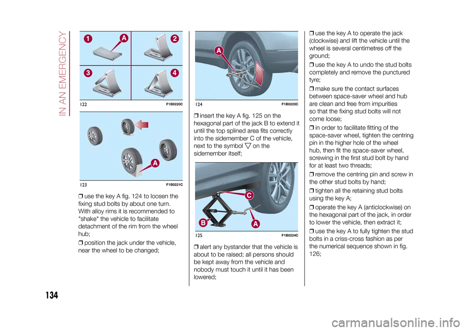
❒use the key A fig. 124 to loosen the
fixing stud bolts by about one turn.
With alloy rims it is recommended to
"shake" the vehicle to facilitate
detachment of the rim from the wheel
hub;
❒position the jack under the vehicle,
near the wheel to be changed;❒insert the key A fig. 125 on the
hexagonal part of the jack B to extend it
until the top splined area fits correctly
into the sidemember C of the vehicle,
next to the symbol
on the
sidemember itself;
❒alert any bystander that the vehicle is
about to be raised; all persons should
be kept away from the vehicle and
nobody must touch it until it has been
lowered;❒use the key A to operate the jack
(clockwise) and lift the vehicle until the
wheel is several centimetres off the
ground;
❒use the key A to undo the stud bolts
completely and remove the punctured
tyre;
❒make sure the contact surfaces
between space-saver wheel and hub
are clean and free from impurities
so that the fixing stud bolts will not
come loose;
❒in order to facilitate fitting of the
space-saver wheel, tighten the centring
pin in the higher hole of the wheel
hub, then fit the space-saver wheel,
screwing in the first stud bolt by hand
for at least two threads;
❒remove the centring pin and screw in
the other stud bolts by hand;
❒tighten all the retaining stud bolts
using the key A;
❒operate the key A (anticlockwise) on
the hexagonal part of the jack, in order
to lower the vehicle, then extract it;
❒use the key A to fully tighten the stud
bolts in a criss-cross fashion as per
the numerical sequence shown in fig.
126;
122
F1B0220C
123
F1B0221C
124
F1B0223C
125
F1B0224C
134
IN AN EMERGENCY
15-12-2014 8:23 Pagina 134
Page 141 of 240

❒connect one end of the cable used
for negative (–) to the negative terminal
(–) of the auxiliary battery;
❒Connect the other end of the cable
used for negative (–) to an engine earth
(a visible metal part of the engine
or gearbox/transmission of the vehicle
with flat battery) away from the battery
and the fuel injection system;
❒start the vehicle engine with the
auxiliary battery, let it run for a
few minutes at idling. Start the engine
of the vehicle with flat battery.
Cable disconnection.Once the engine is started, remove the
leads, reversing the order above.
If after a few attempts the engine does
not start, do not persist but contact
a Fiat Dealership.If it is often necessary to perform an
emergency starting, have the vehicle
battery and the recharging system
checked by a Fiat Dealership.
IMPORTANT Any accessories (e.g.
mobile phones, etc.) connected to the
vehicle power sockets, draw current
even if they are not used. These
devices, if left connected too much time
with engine off, may cause the battery
to drain with following reduction of
its life and/or failure to start the engine.
WARNING
148)Before opening the bonnet, make
sure that the engine is off and that the
ignition key is in the STOP position. Follow
the indications on the plate underneath
the bonnet. We recommend that you
remove the key from the ignition if other
people remain in the vehicle. The vehicle
should always be left after the key has
been removed or turned to the STOP
position. During refuelling, make sure that
the engine is off (and that the ignition key is
in the STOP position).
149)Do not get too close to the radiator
cooling fan: the electric fan may start;
danger of injury. Scarves, ties and other
loose clothing may be pulled by moving
parts.150)Remove any metal objects (e.g. rings,
watches, bracelets), that might cause an
accidental electrical contact and cause
serious injury.
151)Batteries contain acid which may burn
skin and eyes. Batteries produce
hydrogen, which is easily flammable and
explosive. Therefore, keep away flames or
devices which may cause sparks.
WARNING
55)Never use a fast battery-charger to
start the engine as this could damage the
electronic systems of your vehicle,
particularly the ignition and fuel supply
control units.
56)Do not connect the cable to the
negative terminal (–) of the flat battery. The
following spark could lead to battery
explosion and cause serious harm. Only
use the specific earth point; do not use any
other exposed metallic part.
129
F1B0217C
139
15-12-2014 8:23 Pagina 139
Page 143 of 240
❒fully depress the brake pedal and
hold it down;
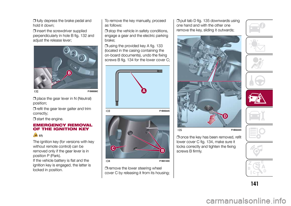
❒insert the screwdriver supplied
perpendicularly in hole B fig. 132 and
adjust the release lever;
❒place the gear lever in N (Neutral)
position;
❒refit the gear lever gaiter and trim
correctly;
❒start the engine.EMERGENCY REMOVAL
OF THE IGNITION KEY
57)
The ignition key (for versions with key
without remote control) can be
removed only if the gear lever is in
position P (Park).
If the vehicle battery is flat and the
ignition key is engaged, the latter is
locked in position.To remove the key manually, proceed
as follows:
❒stop the vehicle in safety conditions,
engage a gear and the electric parking
brake;
❒using the provided key A fig. 133
(located in the casing containing the
on-board documents), undo the fixing
screws B fig. 134 for the lower cover C;
❒remove the lower steering wheel
cover C by releasing it from its housing;❒pull tab D fig. 135 downwards using
one hand and with the other one
remove the key, sliding it outwards;
❒once the key has been removed, refit
lower cover C fig. 134, make sure it
locks correctly and tighten the fixing
screws B firmly.132
F1B0056C
133
F1B0022C
134
F1B0143C
135
F1B0222C
141
15-12-2014 8:23 Pagina 141
Page 144 of 240
WARNING
57)It is advisable to contact a Fiat
Dealership to have the refitting procedure
carried out. If you would like to proceed
autonomously, special attention must
be paid to the correct coupling of
the retaining clips. Otherwise, noise might
be heard due to an incorrect fastening
of the lower cover with the upper cover.
TOWING THE
VEHICLEATTACHING THE TOW
HOOK
153) 154) 155)
The tow hook provided is located in the
tool box inside the boot.FrontProceed as follows:
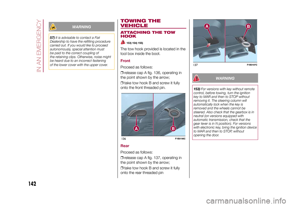
❒release cap A fig. 136, operating in
the point shown by the arrow;
❒take tow hook B and screw it fully
onto the front threaded pin.RearProceed as follows:
❒release cap A fig. 137, operating in
the point shown by the arrow;
❒take tow hook B and screw it fully
onto the rear threaded pin
WARNING
153)For versions with key without remote
control, before towing, turn the ignition
key to MAR and then to STOP without
removing it. The steering column will
automatically lock when the key is
removed and the wheels cannot be
steered. Also check that the gearbox is in
neutral (on versions equipped with
automatic transmission, check that the
gear lever is in N position). For versions
with electronic key, bring the ignition device
to MAR and then to STOP, without
opening the door.
136
F1B0196C
137
F1B0197C
142
IN AN EMERGENCY
15-12-2014 8:23 Pagina 142