2015 FIAT 500X Engine light
[x] Cancel search: Engine lightPage 106 of 240

MANUAL GEARBOX
110)37)
To engage the gears, press the clutch
pedal fully and put the gear lever into
the required position (the diagram
for gear engagement is shown on the
knob ).
To engage 6
th
gear, operate the lever by
pressing it towards the right in order to
avoid engaging 4
th
gear by mistake.
The same applies to the shift from 6
th
to 5
th
gear.
1.4 Turbo MultiAir - 1.6 MultiJet -
2.0 MultiJet versions with manual
gearbox:To engage reverse R from the
neutral position, lift the ring A fig. 90
located under the knob, then move the
lever to the left and then forwards.1.6 E.torQ versions:To engage
reverse R from neutral, lift ring A fig. 90
under the knob and at the same time
move the lever to the right and then
backwards.
IMPORTANT Reverse can only be
engaged when the vehicle is completely
stationary. For 1.6 E.torQ versions:
with the engine running, wait for at least
2 seconds with the clutch pedal fully
depressed before engaging reverse to
prevent damage to the gears and
grating.
IMPORTANT The clutch pedal should
be used only for gear changes. Do
not drive with your foot resting on the
clutch pedal, however lightly. In some
circumstances, the electronic clutch
control could cut in by interpreting the
incorrect driving style as a fault.
WARNING
110)Depress the clutch pedal fully to
change gear correctly. Therefore, the floor
area underneath the pedal unit must not
be obstructed in any way. Ensure that the
floor mat is always laid flat and does not
interfere with use of the pedals.
WARNING
37)Do not drive with your hand resting on
the gear lever as the force exerted, even
if slight, could lead over time to premature
wear of the gearbox internal components.
90
F1B0134C
104
STARTING AND DRIVING
12-1-2015 15:6 Pagina 104
Page 107 of 240

To select the "sequential" mode, move
the lever from D (Drive) to the left: the
position + (upper gear) or – (lower gear)
can be reached; these are unstable
positions, which means that the lever
always returns to the central position.
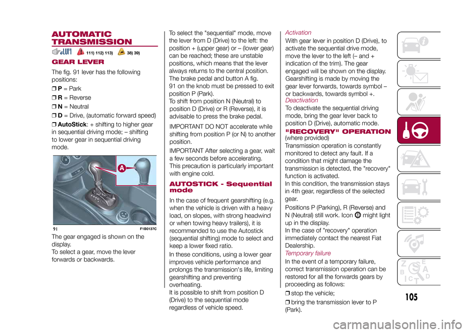
The brake pedal and button A fig.
91 on the knob must be pressed to exit
position P (Park).
To shift from position N (Neutral) to
position D (Drive) or R (Reverse), it is
advisable to press the brake pedal.
IMPORTANT DO NOT accelerate while
shifting from position P (or N) to another
position.
IMPORTANT After selecting a gear, wait
a few seconds before accelerating.
This precaution is particularly important
with engine cold.AUTOSTICK - Sequential
modeIn the case of frequent gearshifting (e.g.
when the vehicle is driven with a heavy
load, on slopes, with strong headwind
or when towing heavy trailers), it is
recommended to use the Autostick
(sequential shifting) mode to select and
keep a lower fixed ratio.
In these conditions, using a lower gear
improves vehicle performance and
prolongs the transmission's life, limiting
gearshifting and preventing
overheating.
It is possible to shift from position D
(Drive) to the sequential mode
regardless of vehicle speed.
ActivationWith gear lever in position D (Drive), to
activate the sequential drive mode,
move the lever to the left (– and +
indication of the trim). The gear
engaged will be shown on the display.
Gearshifting is made by moving the
gear lever forwards, towards symbol –
or backwards, towards symbol +.DeactivationTo deactivate the sequential driving
mode, bring the gear lever back to
position D (Drive), automatic mode."RECOVERY" OPERATION(where provided)
Transmission operation is constantly
monitored to detect any fault. If a
condition that might damage the
transmission is detected, the "recovery"
function is activated.
In this condition, the transmission stays
in 4th gear, regardless of the selected
gear.
Positions P (Parking), R (Reverse) and
N (Neutral) still work. Icon
might light
up in the display.
In the case of "recovery" operation
immediately contact the nearest Fiat
Dealership.
Temporary failureIn the event of a temporary failure,
correct transmission operation can be
restored for all the forwards gears by
proceeding as follows:
❒stop the vehicle;
❒bring the transmission lever to P
(Park).
105
15-12-2014 8:23 Pagina 105
AUTOMATIC
TRANSMISSIONGEAR LEVERThe fig. 91 lever has the following
positions:
❒P= Park
❒R= Reverse
❒N= Neutral
❒D= Drive, (automatic forward speed)
❒AutoStick: + shifting to higher gear
in sequential driving mode; – shifting
to lower gear in sequential driving
mode.
111) 112) 113)
38) 39)
The gear engaged is shown on the
display.
To select a gear, move the lever
forwards or backwards.91
F1B0137C
Page 109 of 240

START&STOP
SYSTEMThe Start&Stop system automatically
stops the engine each time the vehicle
is stationary and starts it again when
the driver wants to move off.
In this way, the vehicle efficiency is
increased, by reducing consumption,
dangerous gas emissions and noise
pollution.
114)40)
OPERATING MODE
Engine stopping mode
Versions with manual gearboxWith the vehicle stopped, the engine
stops with gearbox in neutral and
clutch pedal released.Versions with automatic transmissionWith vehicle at a standstill and brake
pedal pressed, the engine switches off
if the gear lever is in a position other
than R.
In the event of stops uphill, engine
switching off is disabled to make the
"Hill Hold Control" function available
(works only with running engine).The
warning light on the instrument
panel switches on to signal that the
engine was stopped.
Engine restarting mode
Versions with manual gearboxTo restart the engine, press the clutch
pedal.
If the vehicle does not start when the
clutch is pressed, place the gear lever
in neutral and repeat the procedure.
If the problem persists, contact a Fiat
Dealership.Versions with automatic transmissionTo restart the engine, release the brake
pedal.
With brake pressed, if the gear lever is
in automatic mode - D (Drive) - the
engine can be restarted by moving the
lever to R (Reverse) or N (Neutral) or
"AutoStick".
With brake pressed, if the gear lever is
in "AutoStick" mode, the engine can be
restarted by moving the lever to "+" or
"–", or R (Reverse) or N (Neutral).
When the engine has been stopped
automatically, keeping the brake pedal
pressed, the brake can be released
keeping the engine off by quickly
shifting the gear lever to P (Park).
To restart the engine, just move the
lever out of position P.
SYSTEM MANUAL
ACTIVATION/
DEACTIVATIONTo activate/deactivate the system
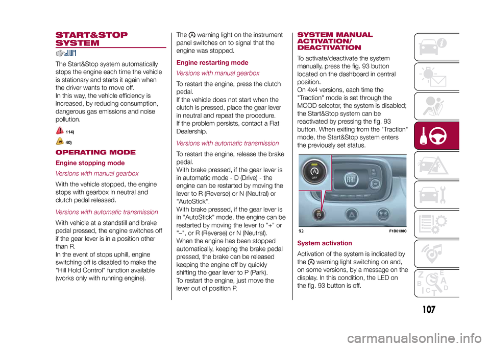
manually, press the fig. 93 button
located on the dashboard in central
position.
On 4x4 versions, each time the
"Traction" mode is set through the
MOOD selector, the system is disabled;
the Start&Stop system can be
reactivated by pressing the fig. 93
button. When exiting from the "Traction"
mode, the Start&Stop system enters
the previously set status.System activationActivation of the system is indicated by
the
warning light switching on and,
on some versions, by a message on the
display. In this condition, the LED on
the fig. 93 button is off.
93
F1B0138C
107
15-12-2014 8:23 Pagina 107
Page 112 of 240

DEACTIVATING THE
DEVICELightly pressing the brake pedal or
pressing the CANC button deactivates
the electronic Cruise Control without
deleting the stored speed.DEACTIVATING THE
DEVICEThe electronic Cruise Control is
deactivated by pressing button A fig. 95
or bringing the ignition device to STOP.
WARNING
115)While travelling with the device
activated, do not move the gear lever to
neutral.
116)In the event of device faults or failures,
go to a Fiat Dealership.
117)The electronic Cruise Control can be
dangerous if the system cannot keep a
constant speed. In specific conditions
speed may be excessive, resulting in the
risk of losing control of the vehicle and
causing accidents. Do not use the device
in heavy traffic or on winding, icy, snowy or
slippery roads.
MOOD SELECTOR
(driving mode
selector)The Mood Selector is a device that
allows the driver to select three different
driving modes (vehicle response)
according to their needs and to the
road and traffic conditions, by manually
adjusting the central tunnel knob ring
nut A fig. 96.- "Auto" mode- "Traction" mode (4x4 or 4x2 versions
depending on the trim level)- "All Weather" mode (only 4x2 versions
depending on the trim level)- "Sport" mode.The device, through the on-board
electronic system, operates on the
vehicle's dynamic control systems:
engine, steering, ESC system, 4x4
system (if available), gearbox/
transmission, and is interfaced with the
instrument panel.
The rotating ring nut is monostable
type. In other words, it always returns
to the central position when released.
The acceptance by the system of
the requested driving mode is signalled
by the LED, located besides the
symbol, coming on, and by the
corresponding symbol appearing on the
instrument panel display.
When the engine is started the system
normally stays in the driving mode
that was active before switching off; for
versions/markets where provided the
system always sets itself to "Auto"
mode at start-up.
96
F1B0044C
110
STARTING AND DRIVING
15-12-2014 8:23 Pagina 110
Page 116 of 240

WARNING
118)Parking and other potentially
dangerous manoeuvres are, however,
always the driver’s responsibility. When
performing these operations, always make
sure that there are no other people
(especially children) or animals on the route
you want to take. The parking sensors are
an aid for the driver, but the driver must
never allow their attention to lapse during
potentially dangerous manoeuvres, even
those executed at low speeds.
WARNING
41)The sensors must be clean of mud,
dirt, snow or ice in order for the system to
operate correctly. Be careful not to scratch
or damage the sensors while cleaning
them. Avoid using dry, rough or hard
cloths. The sensors should be washed
using clean water with the addition of car
shampoo if necessary. When using special
washing equipment such as high pressure
jets or steam cleaning, clean the sensors
very quickly keeping the jet more than
10 cm away.
42)Have interventions on the bumper in
the area of the sensors carried out only by
a Fiat Dealership. Interventions on the
bumper that are not carried out properly
may compromise the operation of the
parking sensors.
LANE ASSIST
SYSTEM (lane
crossing warning)DESCRIPTION
43) 44) 45) 46) 47) 48)
The Lane Assist system makes use of a
camera located on the windscreen to
detect the lane limits and calculate
the position of the vehicle within such
limits, in order to make sure that it
remains inside the lane.
When both limits of the lane are
detected and the vehicle crosses one of
them without the awareness of the
driver (direction indicator off), the Lane
Assist system provides a tactile warning
by applying torque to the steering
wheel (vibration), thus advising the
driver that he must take an action to
remain in the lane.
IMPORTANT The torque applied to the
steering wheel by the system is
sufficient for the driver to notice it, but
always limited, so that they can easily
override it, and the driver always
maintains control of the vehicle. The
driver can therefore turn the steering
wheel as required at all times.If the vehicle continues going beyond
the line of the lane without any
intervention from the driver, the
warning light (or the icon on the
display) will be displayed on the
instrument panel to urge the driver to
bring the vehicle back into the limits of
the lane.
IMPORTANT The system monitors the
presence of the driver's hands on
the steering wheel. If they are
not detected, the system emits an
acoustic signal and deactivates until it is
reactivated by pressing the dedicated
button (see description below).
When one limit of the lane is detected
and the vehicle crosses it (direction
indicator off), warning light
(or the
icon on the display) will be displayed on
the instrument panel to urge the driver
to bring the vehicle back into the lane.
In this case, the tactile warning
(vibration on the steering wheel) is not
provided.
SYSTEM ACTIVATION/
DEACTIVATIONThe Lane Assist system can be
enabled/disabled using button A fig. 98,
located on the left stalk.
Each time the engine is started, the
system keeps the activation status
there was when it was previously
switched off.
114
STARTING AND DRIVING
15-12-2014 8:23 Pagina 114
Page 119 of 240

TOWING TRAILERSIMPORTANT
120) 121)
For towing caravans or trailers the
vehicle must be fitted with an approved
tow hook and an adequate electrical
system. Should aftermarket installation
be requested, this must be carried
out by specialists.
Install any specific and/or additional
door mirrors as specified by the
Highway Code.
Remember that when towing a trailer,
steep hills are harder to climb, braking
distances increase and overtaking
takes longer depending on the overall
weight of the trailer. Engage a low gear
when driving downhill, rather than
constantly using the brake. The weight
the trailer exerts on the vehicle tow
hook reduces the vehicle's loading
capacity by the same amount. To make
sure that the maximum towable weight
is not exceeded (given in the vehicle
registration document) account should
be taken of the fully laden trailer,
including accessories and luggage.
Do not exceed the speed limits specific
to each country you are driving in, in
the case of vehicles towing trailers.
In any case, the top speed must not
exceed 100 km/h.Any electric brake must be powered
directly by the battery through a cable
with a cross-section of no less than 2.5
mm
2. In addition to the electrical
branches, the vehicle electrical system
can only be connected to the supply
cable for an electric brake and to the
cable for an internal light for the trailer,
not exceeding 15 W. For connections,
use the preset control unit with a
battery cable with section not less than
2.5 mm
2. The use of auxiliary loads
other than external lights (e.g. electric
brake) must take place with engine
running.
INSTALLING A TOW
HOOKThe towing device should be fastened
to the body by specialised personnel
according to any additional and/or
integrative information supplied by the
Manufacturer of the device. It must also
meet current regulations with reference
to Directive 94/20/EC and subsequent
amendments.
For any version the towing device used
must be right for the towable weight
of the vehicle on which it is to be
installed.For the electrical connection a standard
connector should be used which is
generally placed on a special bracket
normally fastened to the towing device,
and a special ECU for external trailer
light control must be installed on the
vehicle. 7 or 13-pin 12 V DC
connections should be used (CUNA/
UNI and ISO/DIN Standards). Follow
any instructions provided by the vehicle
manufacturer and/or the towing device
manufacturer.
117
15-12-2014 8:23 Pagina 117
Page 127 of 240

REPLACING AN
EXTERNAL BULB
Dipped/main beam headlightsTo replace the bulb, proceed as follows:
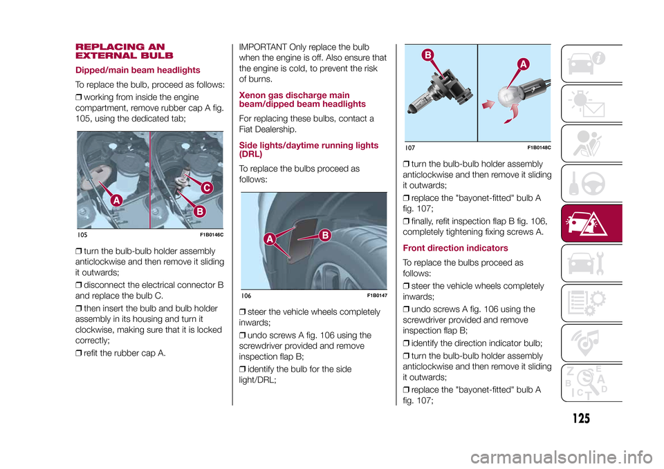
❒working from inside the engine
compartment, remove rubber cap A fig.
105, using the dedicated tab;
❒turn the bulb-bulb holder assembly
anticlockwise and then remove it sliding
it outwards;
❒disconnect the electrical connector B
and replace the bulb C.
❒then insert the bulb and bulb holder
assembly in its housing and turn it
clockwise, making sure that it is locked
correctly;
❒refit the rubber cap A.IMPORTANT Only replace the bulb
when the engine is off. Also ensure that
the engine is cold, to prevent the risk
of burns.
Xenon gas discharge main
beam/dipped beam headlightsFor replacing these bulbs, contact a
Fiat Dealership.Side lights/daytime running lights
(DRL)To replace the bulbs proceed as
follows:
❒steer the vehicle wheels completely
inwards;
❒undo screws A fig. 106 using the
screwdriver provided and remove
inspection flap B;
❒identify the bulb for the side
light/DRL;❒turn the bulb-bulb holder assembly
anticlockwise and then remove it sliding
it outwards;
❒replace the "bayonet-fitted" bulb A
fig. 107;
❒finally, refit inspection flap B fig. 106,
completely tightening fixing screws A.
Front direction indicatorsTo replace the bulbs proceed as
follows:
❒steer the vehicle wheels completely
inwards;
❒undo screws A fig. 106 using the
screwdriver provided and remove
inspection flap B;
❒identify the direction indicator bulb;
❒turn the bulb-bulb holder assembly
anticlockwise and then remove it sliding
it outwards;
❒replace the "bayonet-fitted" bulb A
fig. 107;
105
F1B0146C
106
F1B0147
107
F1B0148C
125
15-12-2014 8:23 Pagina 125
Page 130 of 240

WARNING
51)Halogen bulbs must be handled by
holding the metallic part only. Touching the
transparent part of the bulb with your
fingers may reduce the intensity of the
emitted light and even reduce the lifespan
of the bulb. In the case of accidental
contact, rub the lamp with a cloth and
alcohol and leave to dry.
REPLACING FUSESINTRODUCTION
128) 129) 130) 131)52) 53)
Fuses protect the electrical system:
they intervene (blow) in the event of a
failure or improper action on the
system.Fuse extracting pliersTo replace a fuse, use the pliers hooked
to the side of the engine compartment
fuse box cover (see fig. 114).
The pliers have two different ends,
specifically designed to remove the
different types of fuses present in the
vehicle.
To take out the pliers, grab them from
the upper tabs, press and pull upwards.
After being used, the pliers should be
positioned properly in their housing,
grabbing them from the upper tabs,
pressing and pushing them until a click
is heard.
FUSE LOCATIONFuses are grouped together in the fuse
boxes located in the engine
compartment, under the dashboard
and inside the boot.ENGINE COMPARTMENT
FUSE BOXThe fuse box is located by the side of
the battery fig. 115.
To access the fuses, proceed as
follows:
❒fully tighten screw A fig. 116, using
the screwdriver provided;
❒at the same time slowly rotate the
screw anticlockwise, until resistance is
encountered (do not overtighten);
❒slowly release the screw;
❒opening is indicated by the entire
screw head coming out of its housing;114
F1B0187C
128
IN AN EMERGENCY
15-12-2014 8:23 Pagina 128