2015 FIAT 500L steering wheel
[x] Cancel search: steering wheelPage 213 of 438

Get Started
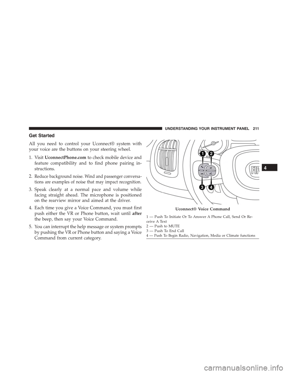
All you need to control your Uconnect® system with
your voice are the buttons on your steering wheel.
1. VisitUconnectPhone.comto check mobile device and
feature compatibility and to find phone pairing in-
structions.
2.Reduce background noise. Wind and passenger conversa-
tions are examples of noise that may impact recognition.
3. Speak clearly at a normal pace and volume while
facing straight ahead. The microphone is positioned
on the rearview mirror and aimed at the driver.
4. Each time you give a Voice Command, you must first
push either the VR or Phone button, wait untilafter
the beep, then say your Voice Command.
5. You can interrupt the help message or system prompts
by pushing the VR or Phone button and saying a Voice
Command from current category.
Uconnect® Voice Command
1—PushToInitiateOrToAnswerAPhoneCall,SendOrRe-ceive A Text2—PushtoMUTE3—PushToEndCall4 — Push To Begin Radio, Navigation, Media or Climate functions
4
UNDERSTANDING YOUR INSTRUMENT PANEL 211
Page 224 of 438

!DRIVING ON SLIPPERY SURFACES.........251
▫Acceleration.........................251
▫Traction............................252
!DRIVING THROUGH WATER.............252
▫Flowing/Rising Water..................253
▫Shallow Standing Water.................253
!ELECTRIC POWER STEERING.............255
!PARKING BRAKE......................255
!BRAKE SYSTEM.......................257
!ELECTRONIC BRAKE CONTROL SYSTEM . . . .257
▫Four-Wheel Anti-Lock Brake System (ABS) . . .257
▫Brake Assist System (BAS)...............259
▫Traction Control System (TCS)............260
▫Hill Start Assist (HSA).................260
▫Dynamic Steering Torque (DST)...........261
▫Electronic Stability Control (ESC)..........262
▫ESC Activation/Malfunction Indicator Light And
ESC OFF Indicator Light................263
▫Electronic Roll Mitigation (ERM)..........265
!TIRE SAFETY INFORMATION.............266
▫Tire Markings........................266
▫Tire Identification Number (TIN)...........270
▫Tire Terminology And Definitions..........271
▫Tire Loading And Tire Pressure...........273
!TIRES — GENERAL INFORMATION........278
▫Tire Pressure........................278
▫Tire Inflation Pressures.................279
222 STARTING AND OPERATING
Page 257 of 438

ELECTRIC POWER STEERING
This only operates with the key turned to MAR/ON and
the engine started. The steering allows the force required
at the steering wheel to be adjusted to suit driving
conditions.
NOTE:When turning the ignition key quickly, full power
steering functionality can be achieved after a few sec-
onds.
PARKING BRAKE
Before leaving the vehicle, make sure that the parking
brake is fully applied. Also, be certain to leave manual
transmission in REVERSE or first gear.
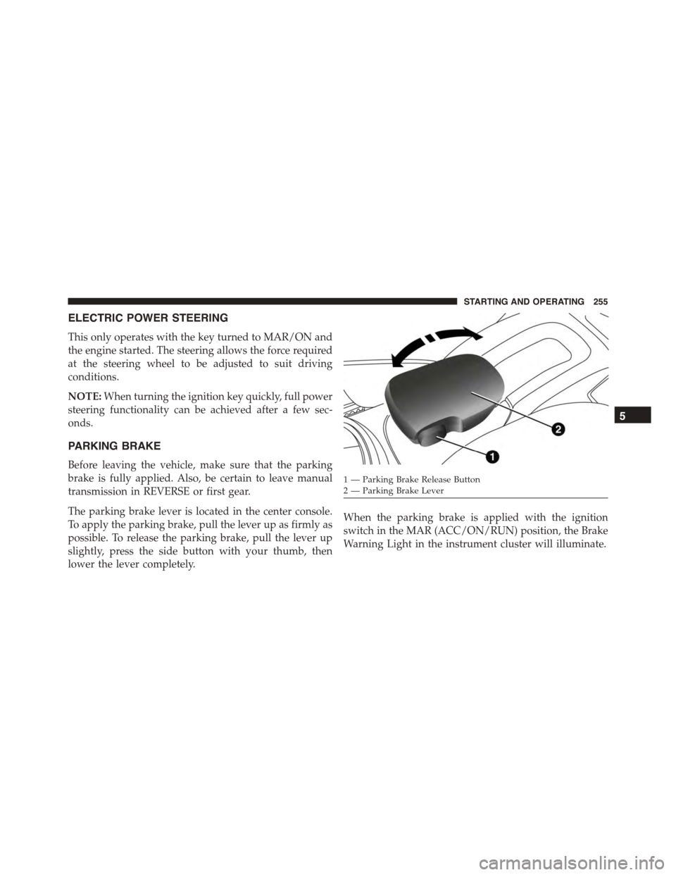
The parking brake lever is located in the center console.
To apply the parking brake, pull the lever up as firmly as
possible. To release the parking brake, pull the lever up
slightly, press the side button with your thumb, then
lower the lever completely.
When the parking brake is applied with the ignition
switch in the MAR (ACC/ON/RUN) position, the Brake
Warning Light in the instrument cluster will illuminate.
1 — Parking Brake Release Button2—ParkingBrakeLever
5
STARTING AND OPERATING 255
Page 259 of 438

CAUTION!
If the Brake Warning Light remains on with the
parking brake released, a brake system malfunction
is indicated. Have the brake system serviced by an
authorized dealer immediately.
BRAKE SYSTEM
Your vehicle is equipped with dual hydraulic brake
systems. If either of the two hydraulic systems loses
normal capability, the remaining system will still func-
tion. However, there will be some loss of overall braking
effectiveness. You may notice increased pedal travel
during application, greater pedal force required to slow
or stop, and potential activation of the “Brake System
Warning Light.”
In the event power assist is lost for any reason (i.e.,
repeated brake applications with the engine off) the
brakes will still function. However, the effort required to
brake the vehicle will be much greater than that required
with the power system operating.
ELECTRONIC BRAKE CONTROL SYSTEM
Your vehicle is equipped with a advanced electronic
brake control system that includes the Anti-Lock Brake
System (ABS), Brake Assist System (BAS), Traction Con-
trol System (TCS), Hill Start Assist (HSA), Dynamic
Steering Torque (DST), and Electronic Stability Control
(ESC). All systems work together to enhance vehicle
stability and control in various driving conditions and
are commonly referred to as ESC.
Four-Wheel Anti-Lock Brake System (ABS)
The Four-Wheel ABS is designed to aid the driver in
maintaining vehicle control under adverse braking con-
ditions. The system operates with a separate computer to
5
STARTING AND OPERATING 257
Page 260 of 438

modulate hydraulic pressure, to prevent wheel lock-up
and to help avoid skidding on slippery surfaces.
The system’s pump motor runs during an ABS stop to
provide regulated hydraulic pressure. The pump motor
makes a low humming noise during operation, which is
normal.
The ABS includes an amber ABS Warning Light. When
the light is illuminated, the ABS is not functioning. The
system reverts to standard non-anti-lock brakes. Turning
the ignition Off and On again may reset the ABS if the
fault detected was only momentary.
WARNING!
•Pumping the Anti-Lock Brakes will diminish their
effectiveness and may lead to a collision. Pumping
makes the stopping distance longer. Just press
firmly on your brake pedal when you need to slow
down or stop.
•The Anti-Lock Brake System (ABS) cannot prevent
the natural laws of physics from acting on the
vehicle, nor can it increase braking or steering
efficiency beyond that afforded by the condition of
the vehicle brakes and tires or the traction afforded.
•The ABS cannot prevent collisions, including those
resulting from excessive speed in turns, following
another vehicle too closely, or hydroplaning.
•The capabilities of an ABS-equipped vehicle must
never be exploited in a reckless or dangerous
manner, which could jeopardize the user’s safety or
the safety of others.
258 STARTING AND OPERATING
Page 263 of 438

•Gear selection matches vehicle uphill direction (i.e.,
vehicle in NEUTRAL (manual transmission), vehicle
facing uphill is in forward gear; vehicle backing uphill
is in REVERSE gear).
WARNING!
There may be situations on minor hills with a loaded
vehicle, or while pulling a trailer, when the system
will not activate and slight rolling may occur. This
could cause a collision with another vehicle or object.
Always remember the driver is responsible for brak-
ing the vehicle.
Disabling/Enabling HSA
If you wish to turn the HSA system on or off, it can be
done using the Customer Programmable Features in the
Electronic Vehicle Information Center (EVIC). Refer to
“Electronic Vehicle Information Center (EVIC)” in “Un-
derstanding Your Instrument Panel” for further informa-
tion.
Dynamic Steering Torque (DST)
The DST function uses the integration of the ESC system
with the electric power steering to increase the safety
level of the whole car.
In critical situations (understeering, oversteering, brak-
ing with different grip conditions), through the DST
function the ESC system controls the steering to imple-
ment an additional torque contribution on the steering
wheel, to suggest the most correct manoeuvre to the
driver.
The coordinated action of brakes and steering increases
the safety and car control feeling.
NOTE:The DST is a driving aid system and does not
replace the driver’s actions while driving the car.
5
STARTING AND OPERATING 261
Page 264 of 438

Electronic Stability Control (ESC)
This system enhances directional control and stability of
the vehicle under various driving conditions. ESC cor-
rects for oversteering or understeering of the vehicle by
applying the brake of the appropriate wheel to assist in
counteracting the oversteering or understeering condi-
tion. Engine power may also be reduced to help the
vehicle maintain the desired path. ESC uses sensors in
the vehicle to determine the vehicle path intended by the
driver and compares it to the actual path of the vehicle.
When the actual path does not match the intended path,
ESC applies the brake of the appropriate wheel to assist
in counteracting the oversteer or understeer condition.
•Oversteer - when the vehicle is turning more than
appropriate for the steering wheel position.
•Understeer - when the vehicle is turning less than
appropriate for the steering wheel position.
WARNING!
The Electronic Stability Control (ESC) cannot pre-
vent the natural laws of physics from acting on the
vehicle, nor can it increase the traction afforded by
prevailing road conditions. ESC cannot prevent all
accidents, including those resulting from excessive
speed in turns, driving on very slippery surfaces, or
hydroplaning. ESC also cannot prevent collisions
resulting from loss of vehicle control due to inappro-
priate driver input for the conditions. Only a safe,
attentive, and skillful driver can prevent accidents.
The capabilities of an ESC equipped vehicle must
never be exploited in a reckless or dangerous manner
which could jeopardize the user ’s safety or the safety
of others.
262 STARTING AND OPERATING
Page 267 of 438

NOTE:To improve the vehicle’s traction when driving
with snow chains, or when starting off in deep snow,
sand, or gravel, it may be desirable to switch to the
“Partial Off” mode by momentarily pressing the “ESC
OFF” button. Once the situation requiring “Partial Off”
mode is overcome, turn ESC back on by momentarily
pressing the “ESC OFF” button. This may be done while
the vehicle is in motion.
WARNING!
When in “Partial Off” mode, the TCS functionality of
ESC (except for the limited slip feature described in
the TCS section) has been disabled and the “ESC Off
Indicator Light” will be illuminated. When in “Par-
tial Off” mode, the engine power reduction of TCS is
disabled, and the enhanced vehicle stability offered
by the ESC system is reduced.
Electronic Roll Mitigation (ERM)
This system anticipates the potential for wheel lift by
monitoring the driver ’s steering wheel input and the
speed of the vehicle. When ERM determines that the rate
of change of the steering wheel angle and vehicle’s speed
are sufficient to potentially cause wheel lift, it then
applies the appropriate brake and may also reduce
engine power to lessen the chance that wheel lift will
occur. ERM will only intervene during very severe or
evasive driving maneuvers.
ERM can only reduce the chance of wheel lift occurring
during severe or evasive driving maneuvers. It cannot
prevent wheel lift due to other factors, such as road
conditions, leaving the roadway, or striking objects or
other vehicles.
5
STARTING AND OPERATING 265