2015 FIAT 500L LIVING ESP
[x] Cancel search: ESPPage 104 of 224
OPERATION WITH A
TRAILERSensor operation is deactivated
automatically when the trailer's electric
cable plug is fitted into the car's tow
hook socket.
The sensors are automatically
reactivated when the trailer's cable plug
is removed.IMPORTANT
INFORMATIONWhen parking, take the utmost care
over obstacles that may be above
or below the sensors.
Under certain circumstances, objects
close to the vehicle are not detected by
the system and could therefore cause
damage to the car or be damaged
themselves.
Some conditions may influence the
performance of the parking sensors:
❒the presence of ice, snow, mud
or think paint on the sensor surface
may cause reduced sensitivity of the
sensor itself and therefore reduce
the system performance.
❒mechanical interference (e.g. washing
the car, rain, strong wind, hail) may
cause the sensor to detect a
non-existent obstacle ("echo
interference");❒the presence of ultrasonic systems
(e.g. pneumatic brake systems of
trucks or pneumatic drills) near the car
could alter the signals sent by the
sensor;
❒the variation in sensor position,
caused by variation in ride (due
to suspension component wear),
changing tyres, overloaded car, or
tuning that lowers the car, for example,
may affect parking sensor system
performance.
WARNING
110)Parking and other dangerous
manoeuvres are, however, always the
driver’s responsibility. While carrying out
these manoeuvres, always make sure that
no people (especially children) or animals
are in the area concerned. The parking
sensors are an aid for the driver, but the
driver must never allow their attention
to lapse during potentially dangerous
manoeuvres, even those executed at low
speeds.
WARNING
59)The sensors must be free from mud,
dirt, snow or ice in order for the system to
operate correctly. Be careful not to scratch
or damage the sensors while cleaning
them. Avoid using dry, rough or hard
cloths. The sensors should be washed
using clean water with the addition of car
shampoo if necessary. When using special
washing equipment such as high pressure
jets or steam cleaning, clean the sensors
very quickly keeping the jet more than
10 cm away. Also, do not apply stickers to
the sensors.
102
STARTING AND DRIVING
9-1-2015 12:9 Pagina 102
Page 105 of 224
REAR VIEW CAMERA
111)
60)
DESCRIPTIONThe camera is located on the tailgate
fig. 98.Camera activation/deactivationUse the "Settings" menu of the
Uconnect™system. When the camera
is activated, whenever reverse is
engaged, the display of the
Uconnect™system shows the image
of the vehicle's rear area.
SYMBOLS AND
MESSAGES ON THE
DISPLAYWhen displayed, the static line grid
illustrates the width of the vehicle.
The grid shows separate areas,
permitting the distance from the rear of
the vehicle to be detected.
The various coloured areas fig. 99
indicate the distance from the rear of
the vehicle.
Red area (A): 0÷30 cmYellow area (B):30cm÷1m
Green area (C):1morhigher
IMPORTANT When parking, take the
utmost care over obstacles that may be
above or under the camera range.
WARNING
111)Parking and other potentially
dangerous manoeuvres are, however,
always the driver’s responsibility. While
carrying out these manoeuvres, always
make sure that no people (especially
children) or animals are in the area
concerned. The camera is an aid for the
driver, but the driver must never allow
his/her attention to lapse during potentially
dangerous manoeuvres, even those
executed at low speeds. Always maintain a
moderate speed, so as to be able to
brake promptly in the case of obstacles.
98
F0Y0336C
99
F0Y0337C
103
9-1-2015 12:9 Pagina 103
Page 106 of 224
WARNING
60)It is extremely important, for correct
operation, that the camera is always kept
clean and free from mud, dirt, snow or ice.
Be careful not to scratch or damage the
camera while cleaning it. Avoid using
dry, rough or hard cloths. The camera
must be washed using clean water, with
the addition of car shampoo if necessary.
In washing stations which use steam or
high-pressure jets, clean the camera
quickly, keeping the nozzle more than 10
cm away. Do not apply stickers to the
camera.
TOWING TRAILERS
112) 113) 114)
INSTALLING A TOW
HOOKThe towing device should be fastened
to the body by specialised personnel
according to any additional and/or
integrative information supplied by the
Manufacturer of the device.
The towing device must meet current
regulations with reference to Directive
94/20/EC and subsequent
amendments.
For any version the towing device used
must be right for the towable weight
of the vehicle on which it is to be
installed.
For the electrical connection a standard
connector should be used which is
generally placed on a special bracket
normally fastened to the towing device,
and a special ECU for external trailer
light control must be installed on the
vehicle.
Seven or thirteen pin 12 V DC
connections should be used (CUNA/
UNI and ISO/DIN Standards). Follow
any instructions provided by the vehicle
manufacturer and/or the towing device
manufacturer.
IMPORTANTFor towing caravans or trailers the car
must be fitted with a type-approved
tow hook and an adequate electrical
system. Installation must be carried out
by a specialist.
Install any specific and/or additional
rear view mirrors as specified by the
Highway Code.
Remember that when towing a trailer,
steep hills are harder to climb, braking
distances increase and overtaking
takes longer depending on the overall
weight of the trail.
Engage a low gear when driving
downhill, rather than constantly using
the brake.
The weight of the trailer on the car's
tow hook will reduce the load capacity
of the car by the same amount. To
make sure that the maximum towable
weight is not exceeded (given in the car
registration document) account should
be taken of the fully laden trailer,
including accessories and luggage.
Respect the speed limits specific to
each country for vehicles towing
trailers. In any case, the top speed
must not exceed 100 km/h.
Any electric brake or other device
(winch etc.) should be powered directly
by the battery through a cable with a
cross-section of no less than 2.5 mm
2.
104
STARTING AND DRIVING
9-1-2015 12:9 Pagina 104
Page 117 of 224
128)You must always indicate that the tyre
was repaired using the Fix&Go Automatic
kit. Give the leaflet to the technicians who
will be handling the tyre that was treated
using the Fix&Go Automatic kit.
129)Repair is not possible if the wheel rim
is damaged (tread is deformed, causing
air to escape). Do not remove foreign
bodies (screws or nails) from the tyre.
130)Do not operate the compressor for
longer than 20 minutes consecutively. Risk
of overheating. The Fix&Go Automatic kit
is not suitable for definitive repairs, so
the repaired tyres may only be used
temporarily.
131)The bottle contains ethylene glycol
and latex: it may cause an allergic reaction.
It is harmful if swallowed. It is irritant for
the eyes. It may cause sensitisation if
inhaled or on contact. Avoid contact with
eyes, skin and clothes. In the case of
contact, wash immediately with plenty of
water. In the event that it is swallowed, do
not induce vomiting. Rinse out your mouth,
drink large quantities of water and seek
immediate medical attention. Keep out of
the reach of children. The product must
not be used by asthmatics. Do not inhale
the vapours during insertion and suction.
Call a doctor immediately if allergic
reactions are noted. Store the bottle in its
proper compartment, away from sources
of heat. The sealant has an expiry date.
Replace the bottle containing out-of-date
sealant.
WARNING
64)In the event of a puncture caused by
foreign bodies, the kit may be used to
repair tyres showing damage on the tread
or shoulder up to max. 4 mm diameter.
WARNING
3)Dispose of the bottle and the sealant
properly. Dispose of the components
in compliance with national and local
regulations.
REPLACING A BULB
132) 133)
65) 66)
GENERAL
INSTRUCTIONS❒Before changing a bulb check the
contacts for oxidation;
❒burnt bulbs must be replaced by
others of the same type and power;
❒after replacing a headlight bulb,
always check the correct alignment of
the light beam;
❒when a light is not working, check
that the corresponding fuse is intact
before changing a bulb. For the location
of fuses, refer to the paragraph “If a
fuse blows” in this section;
115
9-1-2015 12:9 Pagina 115
Page 124 of 224
WARNING
132)Changes or repairs to the electrical
system carried out incorrectly and without
due consideration for the technical
specifications of the system may lead to
malfunctioning and generate a fire hazard.
133)Halogen bulbs contain pressurised
gas. If they break, glass fragments could fly
everywhere.
WARNING
65)Halogen bulbs must be handled by
holding the metallic part only. Touching the
transparent part of the bulb with your
fingers may reduce the intensity of the
emitted light and even reduce the lifespan
of the bulb. In the event of accidental
contact, wipe the bulb with a cloth
moistened with alcohol and leave it to dry.
66)Where possible, it is advisable to
have bulbs changed at a Fiat Dealership.
Proper operation and direction of the
external lights are essential for driving in
safety and comply with law.
REPLACING FUSES
134) 135) 136) 137) 138) 139)
67)
FUSE LOCATIONFuses are grouped together in three
fuse boxes located in the engine
compartment, under the dashboard
and inside the luggage compartment.ENGINE COMPARTMENT
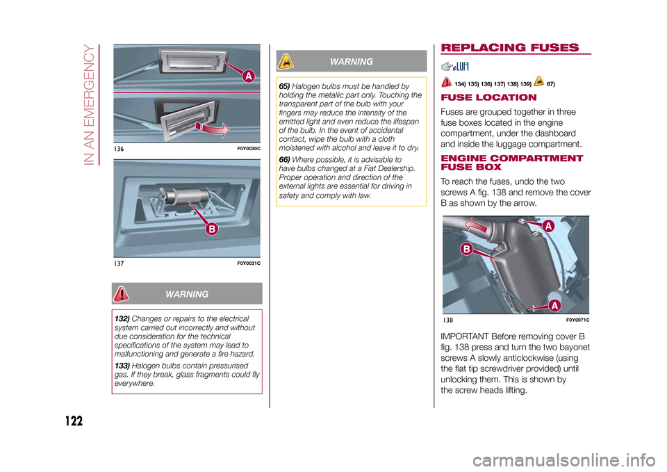
FUSE BOXTo reach the fuses, undo the two
screws A fig. 138 and remove the cover
B as shown by the arrow.
IMPORTANT Before removing cover B
fig. 138 press and turn the two bayonet
screws A slowly anticlockwise (using
the flat tip screwdriver provided) until
unlocking them. This is shown by
the screw heads lifting.
136
F0Y0030C
137
F0Y0031C
138
F0Y0071C
122
IN AN EMERGENCY
9-1-2015 12:9 Pagina 122
Page 133 of 224
146)Whilst towing, remember that the
assistance of the brake servo and the
electric power steering is not available,
therefore greater force needs to be exerted
on the brake pedal and more effort is
required on the steering wheel. Do not use
flexible cables when towing and avoid
jerky movements. Make sure not to
damage parts in contact with the car while
towing. When towing the car, you must
comply with all specific traffic regulations,
both in terms of the towing device and
behaviour on the road. Do not start the
engine while being towed.
147)The front and rear tow hooks should
be used only for emergencies on the road.
The car may be towed for short distances
when a dedicated device is used in
compliance with the Highway Code (rigid
bar), and in order to move the vehicle
on the road in preparation for towing or
transport via a tow truck (on the Trekking
versions do NOT use the rear tow hook for
transport on a tow truck: use the front
tow hook). Tow hooks MUST NOT be used
to tow vehicles off the road or where there
are obstacles and/or for towing operations
using ropes or other non-rigid devices.
Respecting the above conditions, towing
must take place with two vehicles (one
towing, the other towed) aligned as much
as possible along the same centre line.
131
9-1-2015 12:9 Pagina 131
Page 157 of 224
WINDSCREEN/REAR
WINDOW WIPER
162)
75)
REPLACING THE
WINDSCREEN WIPER
BLADESProceed as follows:
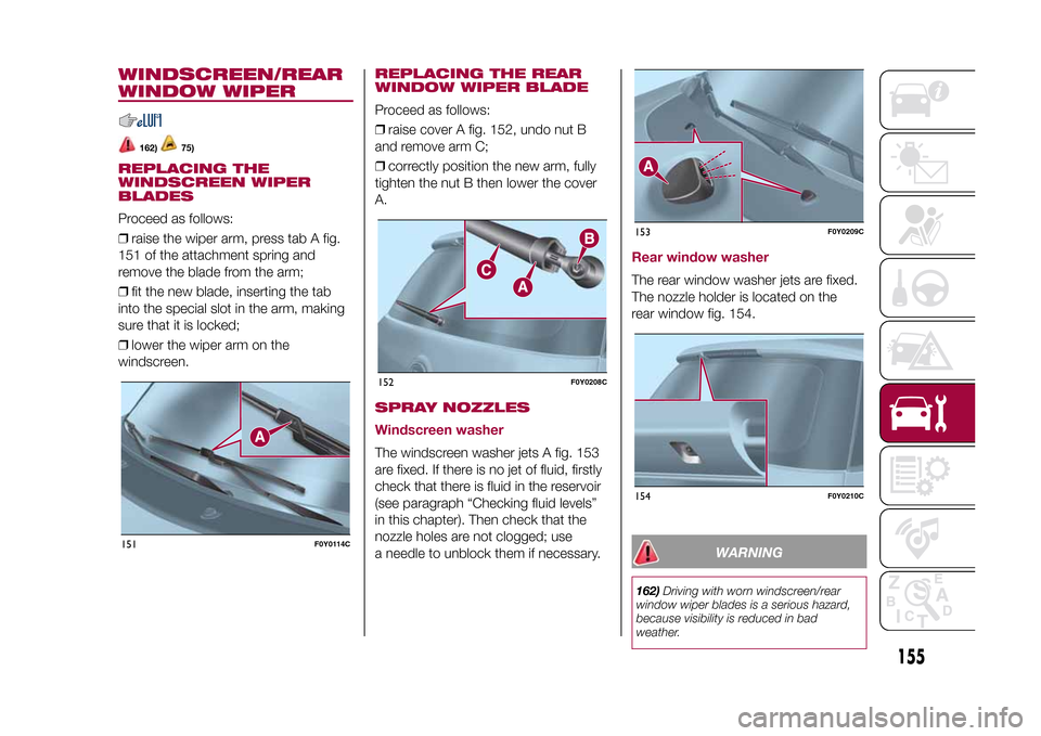
❒raise the wiper arm, press tab A fig.
151 of the attachment spring and
remove the blade from the arm;
❒fit the new blade, inserting the tab
into the special slot in the arm, making
sure that it is locked;
❒lower the wiper arm on the
windscreen.
REPLACING THE REAR
WINDOW WIPER BLADEProceed as follows:
❒raise cover A fig. 152, undo nut B
and remove arm C;
❒correctly position the new arm, fully
tighten the nut B then lower the cover
A.SPRAY NOZZLES
Windscreen washerThe windscreen washer jets A fig. 153
are fixed. If there is no jet of fluid, firstly
check that there is fluid in the reservoir
(see paragraph “Checking fluid levels”
in this chapter). Then check that the
nozzle holes are not clogged; use
a needle to unblock them if necessary.
Rear window washerThe rear window washer jets are fixed.
The nozzle holder is located on the
rear window fig. 154.
WARNING
162)Driving with worn windscreen/rear
window wiper blades is a serious hazard,
because visibility is reduced in bad
weather.
151
F0Y0114C
152
F0Y0208C
153
F0Y0209C
154
F0Y0210C
155
9-1-2015 12:9 Pagina 155
Page 162 of 224
IDENTIFICATION
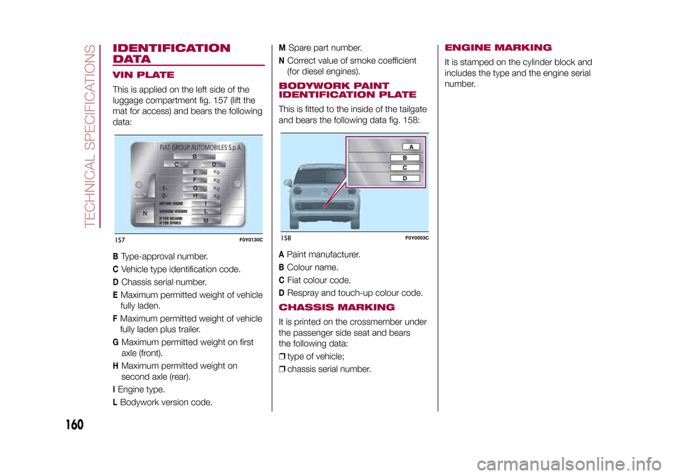
DATAVIN PLATEThis is applied on the left side of the
luggage compartment fig. 157 (lift the
mat for access) and bears the following
data:B
Type-approval number.
C
Vehicle type identification code.
D
Chassis serial number.
EMaximum permitted weight of vehicle
fully laden.FMaximum permitted weight of vehicle
fully laden plus trailer.G
Maximum permitted weight on first
axle (front).
H
Maximum permitted weight on
second axle (rear).
IEngine type.LBodywork version code.
M
Spare part number.
N
Correct value of smoke coefficient
(for diesel engines).
BODYWORK PAINT
IDENTIFICATION PLATEThis is fitted to the inside of the tailgate
and bears the following data fig. 158:A
Paint manufacturer.
B
Colour name.
C
Fiat colour code.
D
Respray and touch-up colour code.
CHASSIS MARKINGIt is printed on the crossmember under
the passenger side seat and bears
the following data:
❒type of vehicle;
❒chassis serial number.
ENGINE MARKINGIt is stamped on the cylinder block and
includes the type and the engine serial
number.
157
F0Y0130C
158
F0Y0003C
160
TECHNICAL SPECIFICATIONS
9-1-2015 12:9 Pagina 160