2015 FIAT 500L LIVING ESP
[x] Cancel search: ESPPage 69 of 224
54)The ESC system cannot alter the
natural laws of physics, and cannot
increase grip which depends on the
condition of the road.
55)The ESC system cannot prevent
accidents, including those due to excessive
speed on corners, driving on low-grip
surfaces or aquaplaning.
56)The capability of the ESC system must
never be tested irresponsibly and
dangerously, in such a way as to
compromise the safety of the driver, the
other occupants of the car or any other
road user.
57)For the correct operation of the ESC
and ASR systems it is extremely important
that the tyres are the same brand and
the same type on all the wheels, in perfect
condition and, above all, the
recommended type and size.
58)The performance of the ESC and ASR
systems must not encourage the driver
to take unnecessary risks. Your driving style
must always be suited to the road
conditions, visibility and traffic. The driver
is, in any case, responsible for safe driving.
59)The ESC functions even when the
space-saver wheel is being used. Always
remember that the space-saver wheel,
being smaller than the original wheel,
provides less grip.
60)The Hill Holder system is not a parking
brake; therefore, never leave the car
without having engaged the handbrake,
turned the engine off and engaged first
gear, so that the vehicle is parked in safe
conditions (for further information read the
"Parking" paragraph in the "Starting and
driving" chapter).61)There may be situations on small
gradients (less than 5%), with car laden, in
which the Hill Holder system may not
activate, causing a slight reversing motion
and increasing the risk of collision with
another vehicle or object. The driver is, in
any case, responsible for safe driving.
62)DST is an aid for driving and does not
relieve the driver of responsibility while
driving the vehicle.
63)The performance of a vehicle with ERM
must never be tested in imprudent or
dangerous ways, with the possibility of
putting the safety of the driver or other
people at risk.
DRIVING
ASSISTANCE
SYSTEMSThe vehicle can be equipped with the
following active safety devices:
❒Traction Plus;
❒City Brake Control - "Collision
Mitigation";
❒iTPMS.
For the operation of the systems, see
the following pages.TRACTION PLUS SYSTEM(for versions/markets, where provided)
The system works as a driving aid,
useful for setting off in poor grip
conditions (snow, ice, mud, etc.), which
allows the drive force to be distributed
optimally on the front axle.
The system acts by braking the wheels
with poor grip (or those slipping more
than the others), transferring the drive
force to those which have greater
grip on the ground.
The activation of the Traction Plus
system generates the differential locking
effect on the front axle through the
braking system, to optimise traction on
irregular terrain.
When the engine is started the system
is deactivated.
67
9-1-2015 12:9 Pagina 67
Page 72 of 224
❒briefly press the
button: the
display will show "Confirm";
❒press the
button or the
button to select ("Yes" to "Reset"
or "No" to exit the screen);
❒hold the
button down again to go
back to the standard screen or to the
main menu according to where you are
in the menu.
Once the "Reset" procedure has been
performed, the display shows a
message indicating that the "self-
learning" procedure has started.
Working conditionsThe system is active for speeds above
15 km/h. In a few situations such as
sporty driving, particular conditions of
the road surface (e.g. icy, snowy,
unsurfaced roads) the signalling may be
delayed, or be partial in the detection
if more tyres are flat simultaneously.
Under special conditions (e.g. vehicle
loaded asymmetrically on one side,
towing a trailer, damaged or worn tyre,
fitting the space-saver wheel, use of the
"Fix&Go Automatic" kit, fitting snow
chains, fitting different tyres on the
axles) the system may give false
indications or be temporarily
deactivated.If the system is temporarily deactivated
the
warning light flashes for about
75 seconds and then is continuously
on; at the same time, the display shows
a dedicated message. This indication
is displayed also after the engine has
been switched off and then on again if
the correct operating conditions are not
restored.
WARNING
64)The system is an aid for the driver, who
must always pay full attention while
driving. The responsibility always rests with
the driver, who must take into account
the traffic conditions in order to drive
in complete safety. The driver must always
maintain a safe distance from the vehicle
in front.
65)If the driver depresses the brake pedal
fully or carries out a fast steering during
system operation, the automatic braking
function may stop (e.g. to allow a possible
manoeuvre to avoid the obstacle).
66)The laser beam is not visible at the
naked eye. Do not look directly, or with
optical instruments (e.g. lenses), at the
laser beam from a distance lower than 10
cm: this may cause damage to the sight.
The laser beam is also present when
the key is at MAR but its operation is off,
not available or manually deactivated
with the display Setup Menu.67)The system intervenes on vehicles
travelling in the same lane. Small sized
vehicles (e.g. bicycles or motorbikes)
or people, animals and things (e.g.
pushchairs) and more in general all those
obstacles with a low reflection of the light
emitted by the laser (e.g. vehicles soiled
with mud) are not taken into consideration.
68)If the car must be placed on a roller
bench (at a speed within 5 and 30 km/h)
for maintenance interventions or if it is
washed in an automatic roller washing
tunnel with an obstacle in the front part
(e.g. another car, a wall or another
obstacle), the system may detect its
presence and activate. In this case the
system must be deactivated through the
display Setup Menu.
WARNING
36)The laser sensor may have limited or
absent operation due to weather
conditions such as: heavy rain, hail, thick
fog, heavy snow, formation of ice layers on
the windscreen.
70
SAFETY
9-1-2015 12:9 Pagina 70
Page 74 of 224
SEAT BELTS
69) 70)
USING THE SEAT BELTSThe driver is responsible for respecting,
and ensuring that all the other
occupants of the vehicle also respect,
the local laws in force in relation to
the use of the seat belts.
Always fasten the seat belts before
setting off.
The seat belt should be worn keeping
the torso straight and rested against
the backrest.
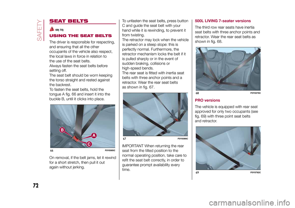
To fasten the seat belts, hold the
tongue A fig. 66 and insert it into the
buckle B, until it clicks into place.
On removal, if the belt jams, let it rewind
for a short stretch, then pull it out
again without jerking.To unfasten the seat belts, press button
C and guide the seat belt with your
hand while it is rewinding, to prevent it
from twisting.
The retractor may lock when the vehicle
is parked on a steep slope: this is
perfectly normal. Furthermore, the
retractor mechanism locks the belt if it
is pulled sharply or in the event of
sudden braking, collisions or
high-speed bends.
The rear seat is fitted with inertia seat
belts with three anchor points and a
retractor. Wear the rear seat belts
as shown in fig. 67.
IMPORTANT When returning the rear
seat from the tilted position to the
normal operating position, take care to
refit the seat belt correctly, in order to
guarantee prompt availability every
time.
500L LIVING 7-seater versionsThe third row rear seats have inertia
seat belts with three anchor points and
retractor. Wear the rear seat belts as
shown in fig. 68.PRO versionsThe vehicle is equipped with rear seat
approved for only two occupants (see
fig. 69) with three point seat belts
and retractor.
66
F0Y0085C
67
F0Y0086C
68
F0Y0379C
69
F0Y0792C
72
SAFETY
9-1-2015 12:9 Pagina 72
Page 76 of 224
PRETENSIONERS
71) 72) 73) 74)
50)
The vehicle is equipped with front seat
belt pretensioners, which draw back
the seat belts by several centimetres in
the event of a strong frontal impact.
This guarantees the perfect adherence
of the seat belts to the occupant's
bodies before the retention action
begins.
It is evident that the pretensioners have
been activated when the belt withdraws
toward the retractor.
This vehicle is also equipped with a
second pretensioner (fitted in the kick
plate area). Its activation is signalled by
the shortening of the metal cable.
A slight discharge of smoke may be
produced during the activation of the
pretensioner which is not harmful and
does not indicate any fire hazard.
The pretensioner does not require any
maintenance or lubrication: any
changes to its original conditions will
invalidate its efficiency.
If, due to unusual natural events (floods,
sea storms, etc.), the device has been
affected by water and/or mud, contact
a Fiat Dealership to have it replaced.IMPORTANT To obtain the highest
degree of protection from the action of
the pretensioner, wear the seat belt
tight to the torso and pelvis.
LOAD LIMITERSTo increase safety in the event of an
accident, the front seat belt retractors
contain a load limiter which controls the
force acting on the chest and
shoulders during the belt restraining
action in the event of a head-on
collision.GENERAL
INSTRUCTIONS FOR
USING THE SEAT BELTSRespect and ensure that all the other
occupants of the vehicle comply with
the local laws in force regarding the use
of seat belts. Always fasten the seat
belts before setting off.
Seat belts must also be worn by
pregnant women: the risk of injury in
the event of an accident is reduced for
them and the unborn child if they are
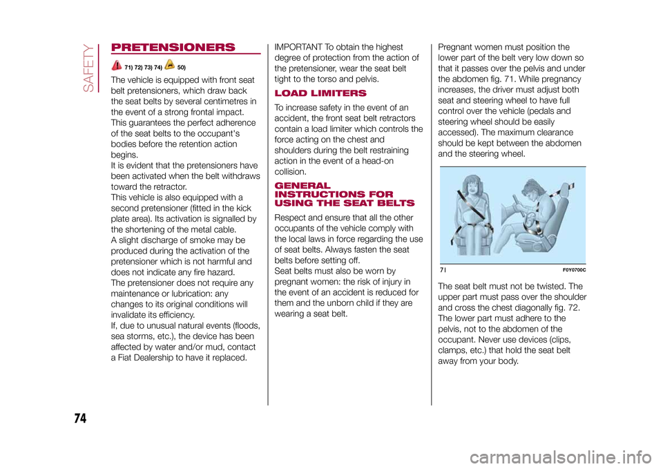
wearing a seat belt.Pregnant women must position the
lower part of the belt very low down so
that it passes over the pelvis and under
the abdomen fig. 71. While pregnancy
increases, the driver must adjust both
seat and steering wheel to have full
control over the vehicle (pedals and
steering wheel should be easily
accessed). The maximum clearance
should be kept between the abdomen
and the steering wheel.
The seat belt must not be twisted. The
upper part must pass over the shoulder
and cross the chest diagonally fig. 72.
The lower part must adhere to the
pelvis, not to the abdomen of the
occupant. Never use devices (clips,
clamps, etc.) that hold the seat belt
away from your body.
71
F0Y0700C
74
SAFETY
9-1-2015 12:9 Pagina 74
Page 79 of 224
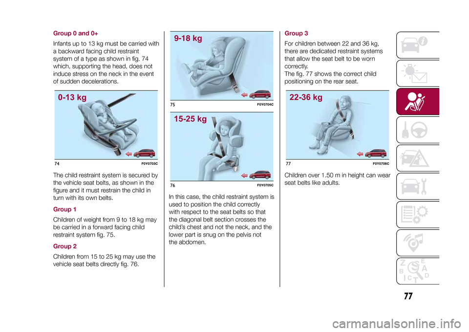
Group 0 and 0+Infants up to 13 kg must be carried with
a backward facing child restraint
system of a type as shown in fig. 74
which, supporting the head, does not
induce stress on the neck in the event
of sudden decelerations.
The child restraint system is secured by
the vehicle seat belts, as shown in the
figure and it must restrain the child in
turn with its own belts.Group 1Children of weight from 9 to 18 kg may
be carried in a forward facing child
restraint system fig. 75.Group 2Children from 15 to 25 kg may use the
vehicle seat belts directly fig. 76.In this case, the child restraint system is
used to position the child correctly
with respect to the seat belts so that
the diagonal belt section crosses the
child’s chest and not the neck, and the
lower part is snug on the pelvis not
the abdomen.
Group 3For children between 22 and 36 kg,
there are dedicated restraint systems
that allow the seat belt to be worn
correctly.
The fig. 77 shows the correct child
positioning on the rear seat.
Children over 1.50 m in height can wear
seat belts like adults.
74
F0Y0703C
75
F0Y0704C
76
F0Y0705C
77
F0Y0706C
77
9-1-2015 12:9 Pagina 77
Page 98 of 224
WARNING
104)Depress the clutch pedal fully to
change gear correctly. Therefore, the floor
area underneath the pedal unit must not
be obstructed in any way. Ensure that the
floor mat is always laid flat and does not
interfere with use of the pedals.
WARNING
56)Do not drive with your hand resting on
the gear lever as the force exerted, even
if slight, could lead over time to premature
wear of the gearbox internal components.
USING THE
DUALOGIC
GEARBOX(for versions/markets, where provided)
105)
57)
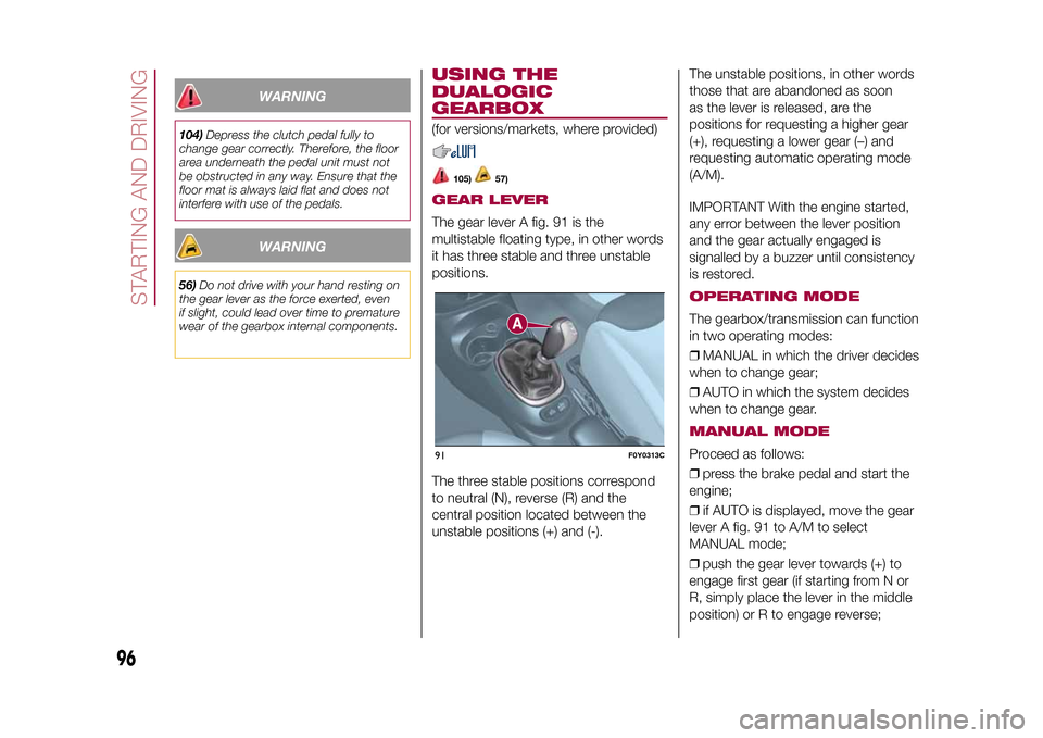
GEAR LEVERThe gear lever A fig. 91 is the
multistable floating type, in other words
it has three stable and three unstable
positions.
The three stable positions correspond
to neutral (N), reverse (R) and the
central position located between the
unstable positions (+) and (-).The unstable positions, in other words
those that are abandoned as soon
as the lever is released, are the
positions for requesting a higher gear
(+), requesting a lower gear (–) and
requesting automatic operating mode
(A/M).
IMPORTANT With the engine started,
any error between the lever position
and the gear actually engaged is
signalled by a buzzer until consistency
is restored.
OPERATING MODEThe gearbox/transmission can function
in two operating modes:
❒MANUAL in which the driver decides
when to change gear;
❒AUTO in which the system decides
when to change gear.MANUAL MODEProceed as follows:
❒press the brake pedal and start the
engine;
❒if AUTO is displayed, move the gear
lever A fig. 91 to A/M to select
MANUAL mode;
❒push the gear lever towards (+) to
engage first gear (if starting from N or
R, simply place the lever in the middle
position) or R to engage reverse;
91
F0Y0313C
96
STARTING AND DRIVING
9-1-2015 12:9 Pagina 96
Page 102 of 224
Restoring the memorised speed:
accelerate gradually until reaching
a speed approaching the memorised
speed, engage the gear selected at the
time of speed memorising and press
the CANC RES button (B fig. 95).INCREASING/
DECREASING
MEMORISED SPEEDSpeed increase: press the accelerator
and memorise the new speed or move
the stalk upwards (+), until reaching
the new speed, which will be
memorised automatically.
Speed decrease: deactivate the
device and memorise the new speed or
move the stalk downwards (-), until
reaching the new speed, which will be
memorised automatically.
Each movement of the stalk
corresponds to an increase/decrease in
speed of about 1 km/h, while keeping
the stalk held upwards will continuously
increase the speed.DEACTIVATING THE
DEVICEThe device can be switched off in the
following ways:
❒turning ring nut A toO;
❒by switching off the engine;❒by pressing the brake pedal, the
clutch or the accelerator; in this last
case the device is not effectively
deactivated, rather it gives priority to
the acceleration request. The device still
remains active, without the need to
press the CANC RES button to return
to the previous conditions once
acceleration is concluded.
Automatic deactivation of the
device: the device deactivates
automatically if the ABS (or ESC)
systems are activated, if the vehicle
speed is below the set limit or in the
case of device failure.
WARNING
108)While travelling with the device
engaged, do not put the gear lever into
neutral.
109)In the case of malfunctioning or if the
device fails, turn ring nut toOand contact
a Fiat Dealership.
SPEED LIMITER(for versions/markets, where provided)DESCRIPTIONThis steering aid device allows the
speed of the vehicle to be limited to
values which can be set by the driver.
The maximum speed can be set both
with vehicle stationary and in motion.
The minimum speed that can be set is
30 km/h.
When the device is active, the vehicle
speed depends on the pressure at
the accelerator pedal, until the set
speed limit is reached. If necessary (in
the event of overtaking for example),
the set speed limit can be exceeded by
fully depressing the accelerator pedal.
By gradually reducing the pressure
on the accelerator pedal, the device will
be reactivated as soon as the car
speed drops below the set speed.ACTIVATING THE DEVICETurn ring nut A fig. 96 to
.
SPEED LIMIT
PROGRAMMINGThe speed limit can be programmed
without necessarily activating the
device.
100
STARTING AND DRIVING
9-1-2015 12:9 Pagina 100
Page 103 of 224
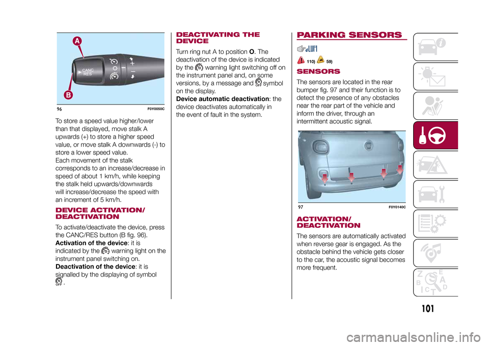
To store a speed value higher/lower
than that displayed, move stalk A
upwards (+) to store a higher speed
value, or move stalk A downwards (-) to
store a lower speed value.
Each movement of the stalk
corresponds to an increase/decrease in
speed of about 1 km/h, while keeping
the stalk held upwards/downwards
will increase/decrease the speed with
an increment of 5 km/h.DEVICE ACTIVATION/
DEACTIVATIONTo activate/deactivate the device, press
the CANC/RES button (B fig. 96).
Activation of the device:itis
indicated by the
warning light on the
instrument panel switching on.
Deactivation of the device:itis
signalled by the displaying of symbol
.
DEACTIVATING THE
DEVICETurn ring nut A to positionO. The
deactivation of the device is indicated
by the
warning light switching off on
the instrument panel and, on some
versions, by a message and
symbol
on the display.
Device automatic deactivation: the
device deactivates automatically in
the event of fault in the system.
PARKING SENSORS
110)
59)
SENSORSThe sensors are located in the rear
bumper fig. 97 and their function is to
detect the presence of any obstacles
near the rear part of the vehicle and
inform the driver, through an
intermittent acoustic signal.ACTIVATION/
DEACTIVATIONThe sensors are automatically activated
when reverse gear is engaged. As the
obstacle behind the vehicle gets closer
to the car, the acoustic signal becomes
more frequent.
96
F0Y0050C
97
F0Y0140C
101
9-1-2015 12:9 Pagina 101