2015 DODGE JOURNEY seats
[x] Cancel search: seatsPage 32 of 140

REAR SEATS
60/40 SPLIT SECOND-ROW PASSENGER SEATS
To Lower The Seatback
•Locatetheseatbackreleaseleveronthe
lower outboard side of the seat.
•Place one hand on the seatback and
apply a gentle pressure.
•Lifttheseatbackreleaseleverwiththe
other hand, allowing the seatback to
move forward slightly, and then release
the lever.
•Gentlyguidetheseatbackintothefolded
position.
To Raise The Seatback
•Raisetheseatbackandlockitinplace.
Forward And Rearward Adjustment
•Thecontrolleverisontheoutboardside
of the seat. Lift the lever to move the seat
forward or rearward. Release the lever
once the seat is in the position desired.
Recliner Adjustment
•Theseatbackreleaseleverisontheoutboardsideoftheseat.Toreclinetheseat,lean
back, lift the lever, position the seatback as desired, and then release the lever. To
return the seatback to its normal upright position, lean back, lift the lever, lean forward,
and then release the lever once the seatback is in the upright position.
Rear Seat Lever Locations
1—Forward/RearwardAdjustmentLever2—Recliner/SeatbackReleaseLever3—Tip’nSlide™ControlLever
GETTING STARTED
30
Page 33 of 140

STADIUM Tip ’n Slide™ (EASY ENTRY/EXIT SEAT) — SEVEN PASSENGER MODELS
To Move The Second-Row Passenger Seat Forward
NOTE:
Raise the 20% seatback/armrest before moving the 60% seat to allow for full seat travel.
•Toallowpassengerstoeasilyenterorexitthethird-rowpassengerseatsmovetheTip’n
Slide™ control lever on the upper outboard side of the seatback forward, and in one
fluid motion, the seat cushion flips upward and the seat moves forward on its tracks.
To Unfold And Move The Second-Row
Passenger Seat Rearward
•Movetheseatbackrearwarduntilitlocks
in place and then continue sliding the
seat rearward on its tracks until it locks in
place.
•Pushtheseatcushiondownwardtolock
it in place.
•Adjusttheseattrackpositionasdesired.
50/50 SPLIT THIRD-ROW PASSENGER SEATS WITH FOLD-FLAT FEATURE
To Fold The Seat
•Withthesecond-rowpassengerseatfullyupright,pullthelatchrelease-looplocatedat
the top of the seatback upward, push the seat forward slightly, and release the
release-loop. Then, continue to push the seat forward. The head restraints will fold
automatically as the seat moves forward.
To Unfold The Seat
•Grasptheassiststraploopontheseatbackandpullittowardyoutoraisetheseatback.
Continue to raise the seatback until it locks in place. Then, raise the head restraint to
lock it in place.
•Tolocktheseatbackinareclinedposition,pullthelatchrelease-looplocatedatthetop
of the seatback upward, allow the seatback to recline, then release the release-loop.
Seat In Tip ‘n Slide™ Position
GETTING STARTED
31
Page 34 of 140

WARNING!
•Becertainthattheseatbackislockedsecurelyintoposition.Otherwise,theseatwill
not provide the proper stability for child seats and/or passengers. An improperly
latched seat could cause you and others to be severely injured or killed.
•Donotallowapassengertositinathirdrowseatwithouthavingtheheadrestraint
unfolded and locked in place or seatback(s) folded flat. Failure to follow this
warning may result in the passengers being severely injured or killed in the event of
acollision.
•DonotdrivethevehiclewiththeseatintheTip'nSlide™position,asitisonly
intended for entering and exiting the third row seats. Failure to follow this warning
may result in you and others being severely injured or killed.
•Becertainthattheseatbackandseatarelockedsecurelyintoposition.Otherwise,
the seat will not provide the proper stability for child seats and/or passengers. An
improperly latched seat could cause you or others to be severely injured or killed.
HEATED SEATS
Front Heated Seats
The front heated seats control buttons are located within the climate or controls screen of
the touchscreen.
•Presstheheatedseatbuttononce to turn the High setting On.
•PresstheheatedseatbuttonasecondtimetoturntheLowsettingOn.
•PresstheheatedseatbuttonathirdtimetoturntheheatingelementsOff.
If the High-level setting is selected, the system will automatically switch to Low-level after
approximately 60 minutes. The Low-level setting will turn Off automatically after approxi-
mately 45 minutes.
NOTE:
Vehicle Equipped With Remote Start
On models that are equipped with remote start, this feature can be programmed to come
on during a remote start through the Uconnect®system. Refer to “Uconnect®Settings”
in “Understanding Your Instrument Panel” in the Owner's Manual on the DVD.
GETTING STARTED
32
Page 79 of 140

Compass Calibration
This compass is self-calibrating, which eliminates the need to set the compass manually.
When the vehicle is new, the compass may appear erratic and the EVIC will display “CAL”
until the compass is calibrated.
Yo u m a y a l s o c a l i b r a t e t h e c o m p a s s b y c o m p l e t i n g o n e o r m o r e 3 6 0 d e g r e e t u r n s ( i n a n
area free from large metal or metallic objects) until the “CAL” message displayed in the
EVIC turns off. The compass will now function normally.
PROGRAMMABLE FEATURES
Electronic Vehicle Information Center (EVIC) — If Equipped
•TheEVICcanbeusedtovieworchangethefollowingsettings.PushtheUPor
DOWNbutton until System Setup displays, then push the SELECTbutton.
Scroll through the settings using the UP or DOWN buttons. Push the SELECT
button to change the setting. Push the BACK button to scroll back to a previous menu
or sub menu.
•Fuel Economy•Average Fuel Economy•DistanceToEmpty(DTE)•MilesPerGallon(MPG)
•Tr i p I n f o•Tr i p A•TripB•ElapsedTime
•Vehicle Speed•Ti r e P S I
•Messages•VehicleInfo(CustomerInformation
Features)
Uconnect® 4.3 Customer Programmable Features
•TheUconnect®4.3 system allows you to access Customer Programmable feature
settings such as Display, Clock, Safety/Assistance, Lights, Doors & Locks, Heated
Seats, Engine Off Operation, Compass Settings, Audio, Phone/ Bluetooth®and SIRIUS
Setup through buttons on the faceplate and buttons on the touchscreen.
•Pressthe“Settings”buttonontherightsideoftheunittoaccesstheSettingsscreen,
use the “Page Up/Down” buttons on the touchscreen to scroll through the following
settings. The following feature settings are available:
•Display•AutoOnComfort&RemoteStart
•Clock•EngineOffOptions
•Safety/Assistance•Audio
•Lights•Phone/Bluetooth®
•Doors&Locks•SIRIUSSetup
ELECTRONICS
77
Page 80 of 140

Uconnect® 8.4 Customer Programmable Features
•TheUconnect®8.4 system allows you to access Customer Programmable feature
settings such as Display, Clock, Safety/Assistance, Lights, Doors & Locks, Heated
Seats, Engine Off Operation, Compass Settings, Audio, Phone/Bluetooth®and SIRIUS
Setup through buttons on the touchscreen.
•Pressthe“More”buttononthebottomofthetouchscreen,thenpressthe“Settings”
button on the faceplate to access the Settings screen. When making a selection, scroll
up or down until the preferred setting is highlighted, then press and release the
preferred setting until a check-mark appears next to the setting, showing that setting
has been selected. The following feature settings are available:
•Display•AutoOnComfort&RemoteStart
•Clock•EngineOffOptions
•Safety/Assistance•Audio
•Lights•Phone/Bluetooth®
•Doors&Locks•SIRIUSSetup
UNIVERSAL GARAGE DOOR OPENER (HomeLink®)
•HomeLink®replaces up to three hand-held transmitters that operate devices such as
garage door openers, motorized gates, lighting or home security systems. The
HomeLink®unit is powered by your vehicles 12 Volt battery.
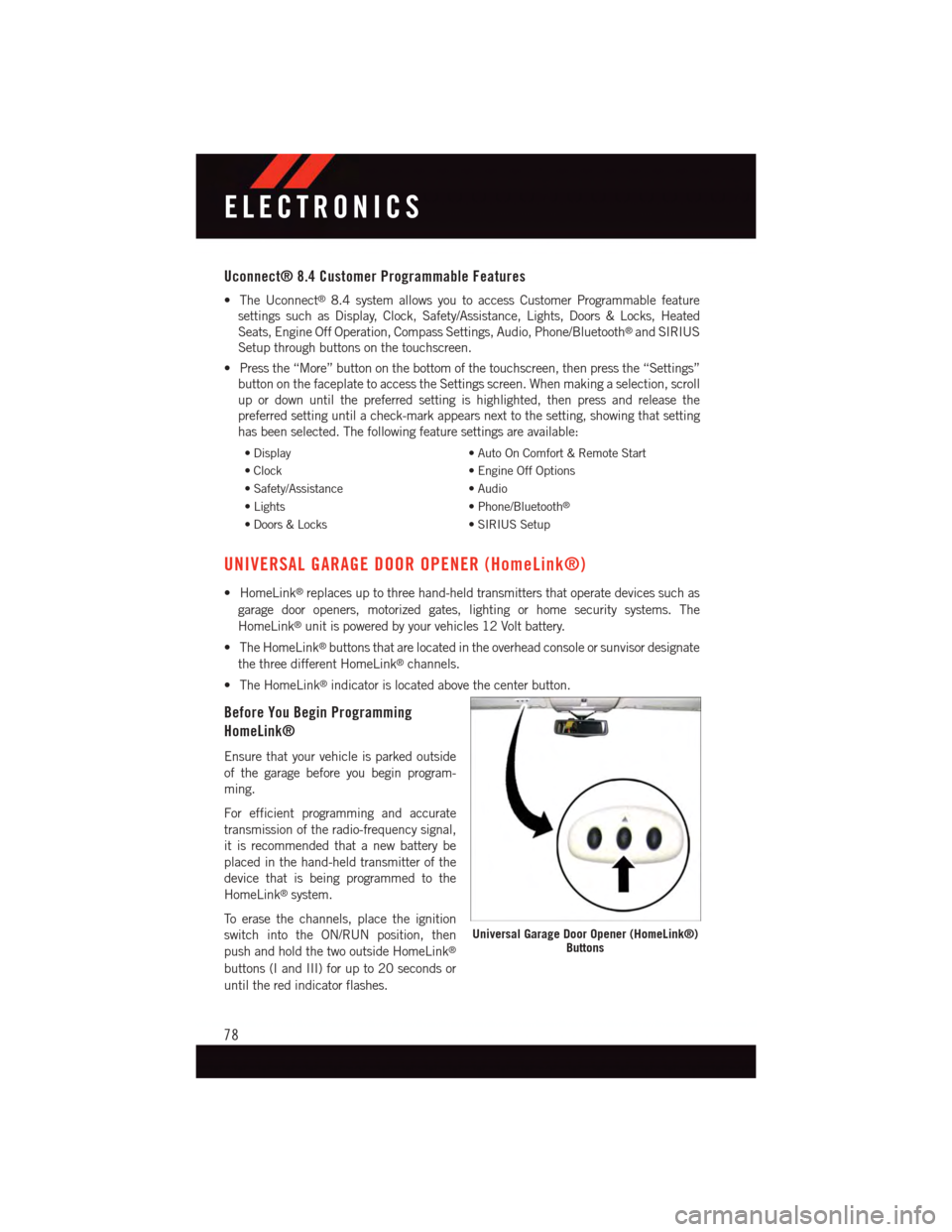
•TheHomeLink®buttons that are located in the overhead console or sunvisor designate
the three different HomeLink®channels.
•TheHomeLink®indicator is located above the center button.
Before You Begin Programming
HomeLink®
Ensure that your vehicle is parked outside
of the garage before you begin program-
ming.
For efficient programming and accurate
transmission of the radio-frequency signal,
it is recommended that a new battery be
placed in the hand-held transmitter of the
device that is being programmed to the
HomeLink®system.
To e r a s e t h e c h a n n e l s , p l a c e t h e i g n i t i o n
switch into the ON/RUN position, then
push and hold the two outside HomeLink®
buttons (I and III) for up to 20 seconds or
until the red indicator flashes.
Universal Garage Door Opener (HomeLink®)Buttons
ELECTRONICS
78
Page 97 of 140

Spare Tire Removal
NOTE:
On seven-passenger models, fold the third-row passenger seats flat. This will provide more
space when accessing the jacking tools and when operating the winch mechanism.
1. Remove the jack-handle components 1, 2 and 3 from storage and assemble them.
NOTE:
Assemble components 2 and 3 by seating the
small ball at the end of component 2 in the
small hole at the end of component 3. This
will lock these components together. As-
semble components 1 and 2 so that the
wheel nut socket at the end of component 1
faces upward when seated on component 2.
This will make it easier to rotate the assembly
when operating the winch mechanism.
2. Fit the assembled jack-handle over the
winch drive nut located in the jack stor-
age area. Rotate the jack-handle assem-
bly counterclockwise until the spare tire
is on the ground with enough cable slack
to allow you to pull the spare tire out
from underneath the vehicle.
3. Pull the spare tire out from underneath the vehicle and raise it upright so the tire's
tread is on the ground.
4. Tilt the retainer at the end of the winch cable and remove it from the center of the
wheel.
Spare Tire Stowage
NOTE:
Refer to “Spare Tire Removal” for information on assembling the winch tools.
1. Place the spare tire near to the winch cable. Hold the spare upright so that the tire's
tread is on the ground and the valve stem is at the top of the wheel facing away from
the rear of the vehicle.
2. Tilt the retainer at the end of the winch cable and drop it through the center of the
wheel. Then place the spare tire with the cable and retainer underneath the vehicle.
3. Fit the assembled jack-handle over the winch drive nut. Rotate the jack-handle
assembly clockwise to raise the spare tire into the storage area. Continue to rotate the
jack-handle assembly until you hear the winch mechanism click three times. It cannot
be over tightened. Push against the tire several times to be sure it is held securely in
place.
Jack-Handle/Components Assembled
1—JackHandle2—Component23—Component3
WHAT TO DO IN EMERGENCIES
95
Page 121 of 140

FUSES
Interior Fuses
The interior fuse panel is located on the passenger side under the instrument panel.
Cavity Cartridge Fuse Mini-FuseDescription
F100 30 Amp Pink–110V AC Inverter – If Equipped
F101–10 Amp RedInterior Lights
F102–20AmpYellowCigar Lighter in Instrument Panel/Left Rear Power Outlet
F103–20AmpYellowPower Outlet in Console Bin/PowerOutlet in Rear of Console
F105–20AmpYellowHeatedSeats–IfEquipped
F106–20AmpYellowRear Power Outlet
F107–10 Amp Red Rear Camera – If Equipped
F108–15 Amp BlueInstrument Panel
F109–10 Amp RedClimate Control/HVAC
F110–10 Amp Red Occupant Restraint Controller
F112–10 Amp RedSpare
F114–20AmpYellowRearHVACBlower/Motor
F115–20AmpYellowRear Wiper Motor
F116 30 Amp Pink–Rear Defroster (EBL)
F117–10 Amp RedHeated Mirrors
F118–10 Amp Red Occupant Restraint Controller
F119–10 Amp Red Steering Column Control Module
F120–10 Amp Red All Wheel Drive – If Equipped
F121–15 Amp Blue Wireless Ignition Node
F122–25 Amp ClearDriver Door Module
F123–25 Amp Clear Passenger Door Module
F124–10 Amp RedMirrors
F125–10 Amp Red Steering Column Control Module
F126–25 Amp ClearAudio Amplifier
F127–20AmpYellowTrailerTow–IfEquipped
F128–15 Amp BlueRadio
F129–15 Amp Blue Video/DVD – If Equipped
F130–15 Amp Blue Climate Control/Instrument Panel
F131–10 Amp RedPassenger Assistance/Hands FreeSystem – If Equipped
F132–10 Amp RedTi r e P r e s s u r e M o d u l e
F133–10 Amp RedSpare
MAINTAINING YOUR VEHICLE
119
Page 131 of 140

FREQUENTLY ASKED QUESTIONS
GETTING STARTED
•HowdoIinstallmyLATCHEquippedChildSeat?pg.21
•HowdoImovemyrearseats?pg.30
ELECTRONICS
•HowdoIknowwhichradioIhave?
•Uconnect®4.3 & 4.3S pg. 49
•Uconnect®8.4 & 8.4N pg. 51
•HowdoIselecttheAUXmusicsource?pg.65
•HowdoIsettheclockonmyradio?
•Uconnect®4.3 & 4.3S pg. 49
•Uconnect®8.4 & 8.4N pg. 51
•HowdoIusetheNavigationfeature?pg.59
•HowdoIpairmycellphoneviaBluetooth®with the Uconnect®Hands-Free Voice
Activation System? pg. 66
•HowdoIheartheaudiofrommyiPod®through the USB port using the radio?
•Uconnect®4.3 & 4.3S pg. 65
•Uconnect®8.4, 8.4N pg. 65
•HowdoIconfiguremyUniversalGarageDoorOpener(HomeLink®)? pg. 78
UTILITY
•HowdoIknowhowmuchIcantowwithmyDodgeJourney?pg.84
WHAT TO DO IN EMERGENCIES
•WhatdoIdoifmyTPMSwarninglightisblinking?pg.87
•HowdoIchangeaflattire?pg.93
•HowdoIJump-Startmyvehicle?pg.101
MAINTAINING YOUR VEHICLE
•WhereismyFuseBlocklocated?
•InteriorFusespg.119
•UnderhoodFusespg.120
•WhattypeofoildoIuse?pg.112
•HowoftenshouldIchangemyengine’soil?pg.114
•Whatshouldmytirepressurebesetat?pg.121
FREQUENTLY ASKED QUESTIONS
129