Page 272 of 703

CAUTION!
•Do not exceed the maximum power of 160 Watts (13
Amps) at 12 Volts. If the 160 Watt (13 Amp) power
rating is exceeded the fuse protecting the system
will need to be replaced.
•Power outlets are designed for accessory plugs
only. Do not insert any other object in the power
outlets as this will damage the outlet and blow the
fuse. Improper use of the power outlet can cause
damage not covered by your New Vehicle Limited
Warranty.
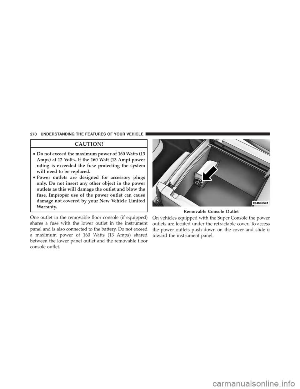
One outlet in the removable floor console (if equipped)
shares a fuse with the lower outlet in the instrument
panel and is also connected to the battery. Do not exceed
a maximum power of 160 Watts (13 Amps) shared
between the lower panel outlet and the removable floor
console outlet.
On vehicles equipped with the Super Console the power
outlets are located under the retractable cover. To access
the power outlets push down on the cover and slide it
toward the instrument panel.
Removable Console Outlet
270 UNDERSTANDING THE FEATURES OF YOUR VEHICLE
Page 274 of 703
WARNING!
To avoid serious injury or death:
•Only devices designed for use in this type of outlet
should be inserted into any 12 Volt outlet.
•Do not touch with wet hands.
•Close the lid when not in use and while driving the
vehicle.
•If this outlet is mishandled, it may cause an electric
shock and failure.
Power Outlet Fuses
1 — M7 Fuse 20 A Yellow Power Outlet Center Seat (Opt) or withConsole Rear2 — M6 Fuse 20 A Yellow Cigar Lighter Instrument Panel or withConsole Front3 — M36 Fuse 20 A Yellow Power Outlet Instrument Panel orwith Console Center
272 UNDERSTANDING THE FEATURES OF YOUR VEHICLE
Page 314 of 703

6. Odometer Display/Electronic Vehicle Information
Center (EVIC) — If Equipped
Odometer Display / Trip Odometer DisplayThe odom-
eter display shows the total distance the vehicle has been
driven.
U.S. Federal regulations require that upon transfer of
vehicle ownership, the seller certify to the purchaser the
correct mileage that the vehicle has been driven. If your
odometer needs to be repaired or serviced, the repair
technician should leave the odometer reading the same
as it was before the repair or service. If s/he cannot do so,
then the odometer must be set at zero, and a sticker must
be placed in the door jamb stating what the mileage was
before the repair or service. It is a good idea for you to
make a record of the odometer reading before the repair/
service, so that you can be sure that it is properly reset, or
that the door jamb sticker is accurate if the odometer
must be reset at zero.
This also displays Trip A and Trip B, DTE, MPG or
L/100km, OAT (Outside Air Temperature) information to
Base Cluster, use STEP and RESET button (on steering
wheel) to access or reset the display.
Message Display Area
When the appropriate conditions exist, the following
odometer messages will display:
door.............................Door Ajar
gATE..........................Liftgate Ajar
LoW tirE....................LowTirePressure
gASCAP......................Fuel Cap Fault
noFUSE..........................Fuse Fault
312 UNDERSTANDING YOUR INSTRUMENT PANEL
Page 315 of 703

CHAngE OIL..............OilChange Required
LoCOOL.......................LowCoolant
NOTE:Some of the above warnings will be displayed in
the Electronic Vehicle Information Center Display Area
located in the instrument cluster.
Refer to ”Electronic Vehicle Information Center (EVIC) —
If Equipped” in this section for further information.
LoW tirE
When the appropriate condition exists, the odometer
display will toggle between LoW and tirE for three
cycles.
gASCAP
If the vehicle diagnostic system determines that the fuel
filler cap is loose, improperly installed, or damaged, a
“gASCAP” message will display in the odometer display
area. Tighten the fuel filler cap properly and push the
STEP button on the steering wheel to turn off the
message. If the problem continues, the message will
appear the next time the vehicle is started.
noFUSE
If the vehicle diagnostic system determines that the
Ignition Off Draw (IOD) fuse is improperly installed, or
damaged, a “noFUSE” message will display in the odom-
eter display area. For further information on fuses and
fuse locations refer to “Fuses” in “Maintaining Your
Vehicle”.
CHAngE OIL
Your vehicle is equipped with an engine oil change
indicator system. TheCHAngE OILmessage will flash in
the instrument cluster odometer for approximately 12
seconds, after a single chime has sounded, to indicate the
next scheduled oil change interval. The engine oil change
4
UNDERSTANDING YOUR INSTRUMENT PANEL 313
Page 608 of 703
▫Appearance Care And Protection From
Corrosion...........................635
▫Cleaning The Instrument Panel Cupholders . .641
!FUSES..............................641
▫Totally Integrated Power Module (Fuses) . . . .642
!VEHICLE STORAGE....................649
!REPLACEMENT BULBS.................650
!BULB REPLACEMENT..................652
▫Headlamps.........................652
▫Front Park/Turn Signal Lamps............652
▫Fog Lamps..........................653
▫Rear Tail, Stop, Turn Signal, Side Marker And
Backup Lamps.......................654
▫Center High-Mounted Stop Lamp (CHMSL) . .655
▫License Lamp........................655
!FLUID CAPACITIES....................656
!FLUIDS, LUBRICANTS AND GENUINE PARTS . .657
▫Engine.............................657
▫Chassis............................659
606 MAINTAINING YOUR VEHICLE
Page 609 of 703
ENGINE COMPARTMENT — 3.6L
1—AirFilter6—EngineCoolantReservoir2 — Power Steering Fluid Reservoir7 — Engine Oil Dipstick3 — Brake Fluid Reservoir8 — Engine Oil Fill4 — Battery9 — Coolant Pressure Cap5 — Totally Integrated Power Module (Fuses)10 — Washer Fluid Reservoir
7
MAINTAINING YOUR VEHICLE 607
Page 643 of 703

Cleaning The Instrument Panel Cupholders
Removal
Pull the flexible liner from the cupholder drawer starting
at one edge to ease removal.
Cleaning
The liner is top shelf dishwasher safe, or you may follow
the cleaning procedure below.
Soak the liner in a mixture of medium hot tap water and
one teaspoon of mild liquid dish soap. Let soak for
approximately 30 minutes. After 30 minutes, pull the
liner from the water and dip it back into the water about
six times. This will loosen any remaining debris. Rinse
the liner thoroughly under warm running water. Shake
the excess water from the liner and dry the outer surfaces
with a clean soft cloth.
Installation
Place the liner into the cupholder drawer and press the
liner into place so that the retention tabs seat into the
corresponding openings in the drawer.
FUSES
WARNING!
•When replacing a blown fuse, always use an ap-
propriate replacement fuse with the same amp
rating as the original fuse. Never replace a fuse
with another fuse of higher amp rating. Never
replace a blown fuse with metal wires or any other
material. Failure to use proper fuses may result in
serious personal injury, fire and/or property dam-
age.
(Continued)
7
MAINTAINING YOUR VEHICLE 641
Page 644 of 703
WARNING!(Continued)
•Before replacing a fuse, make sure that the ignition
is off and that all the other services are switched off
and/or disengaged.
•If the replaced fuse blows again, contact an autho-
rized dealer.
•If a general protection fuse for safety systems (air
bag system, braking system), power unit systems
(engine system, gearbox system) or steering system
blows, contact an authorized dealer.
Totally Integrated Power Module (Fuses)
The Totally Integrated Power Module is located in the
engine compartment near the battery. Refer to the appli-
cable “Engine Compartment” illustration in this section.
This center contains cartridge fuses and mini-fuses. A
label that identifies each component may be printed or
embossed on the inside of the cover.
Totally Integrated Power Module
642 MAINTAINING YOUR VEHICLE