2015 DODGE DURANGO ignition
[x] Cancel search: ignitionPage 141 of 236
NOTE:
•TheUconnect®Phone requires a mobile phone equipped with the Bluetooth®
Hands-Free Profile, Version 1.0 or higher.
•Mostmobilephones/devicesarecompatiblewiththeUconnect®system, however
some mobile phones/devices may not be equipped with all of the required features to
utilize all of the Uconnect®system features.
•ForUconnect®Customer Care:
•U.S.residentsvisitUconnectPhone.comorcall1-877-855-8400.
•CanadianResidentsvisitUconnectPhone.comorcall,1-800-465-2001(English)or
1-800-387-9983 (French).
Pairing (Wirelessly Connecting) Your Mobile Phone To The Uconnect® System
Mobile phone pairing is the process of establishing a wireless connection between a
cellular phone and the Uconnect®system.
NOTE:
•To u s e t h e U c o n n e c t®Phone feature, you first must determine if your mobile phone and
software are compatible with the Uconnect®system. Please visitUconnectPhone.com for
complete mobile phone compatibility information.
•Mobilephonepairingisnotavailablewhilethevehicleisinmotion.
•Amaximumof10mobilephonescanbepairedtotheUconnect®system.
Start Pairing Procedure On The Radio
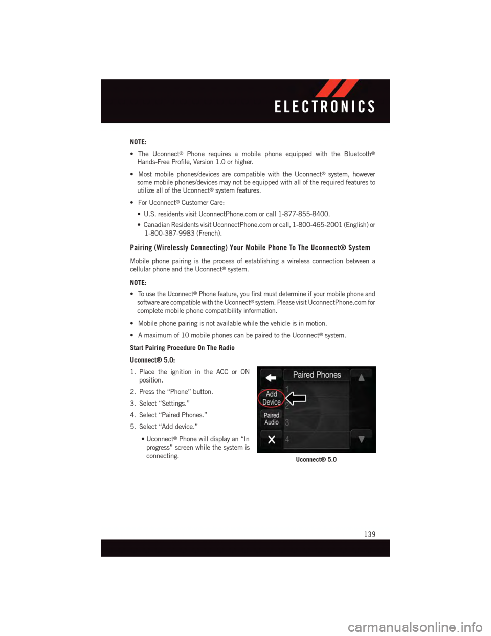
Uconnect® 5.0:
1. Place the ignition in the ACC or ON
position.
2. Press the “Phone” button.
3. Select “Settings.”
4. Select “Paired Phones.”
5. Select “Add device.”
•Uconnect®Phone will display an “In
progress” screen while the system is
connecting.Uconnect® 5.0
ELECTRONICS
139
Page 142 of 236

Uconnect® 8.4A, 8.4AN:
1. Place the ignition in the ACC or ON
position.
2. Press the “Phone” button in the Menu
Bar on the touchscreen.
3. Select “Settings.”
4. Select “Paired Phones.”
5. Select “Add device.”
•Uconnect®Phone will display an “In
progress” screen while the system is
connecting.
Pair Your iPhone®:
To s e a r c h f o r a v a i l a b l e d e v i c e s o n y o u r
Bluetooth®enabled iPhone®:
1. Press the Settings button.
2. Select Bluetooth®.
•EnsuretheBluetooth®feature is en-
abled. Once enabled, the mobile
phone will begin to search for
Bluetooth®connections.
3. When your mobile phone finds the
Uconnect®system, select “Uconnect.”
Complete The iPhone® Pairing Procedure:
1. When prompted on the mobile phone,
accept the connection request from
Uconnect®Phone.
NOTE:
Some mobile phones will require you to
enter the PIN number.
Uconnect® 8.4A & 8.4AN
Bluetooth® On/Uconnect Device
Pairing Request
ELECTRONICS
140
Page 146 of 236

NOTE:
Only incoming text messages received during the current ignition cycle can be viewed/read.
To e n a b l e i n c o m i n g t e x t m e s s a g i n g :
iPhone®
1. Press the settings button on the mobile phone.
2. Select Bluetooth®.
•Ensure Bluetooth is enabled, and the mobile phone is paired to the Uconnect®
system.
3. Selectlocated under DEVICES next to Uconnect.
4. Turn “Show Notifications” to On.
Enable iPhone® Incoming Text Messages
ELECTRONICS
144
Page 147 of 236
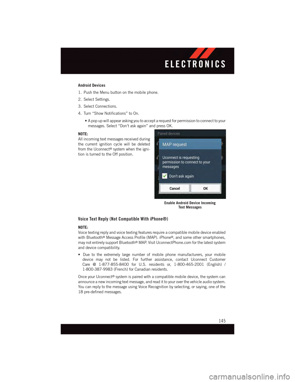
Android Devices
1. Push the Menu button on the mobile phone.
2. Select Settings.
3. Select Connections.
4. Turn “Show Notifications” to On.
•Apopupwillappearaskingyoutoacceptarequestforpermissiontoconnecttoyour
messages. Select “Don’t ask again” and press OK.
NOTE:
All incoming text messages received during
the current ignition cycle will be deleted
from the Uconnect®system when the igni-
tion is turned to the Off position.
Voice Text Reply (Not Compatible With iPhone®)
NOTE:
Voice texting reply and voice texting features require a compatible mobile device enabled
with Bluetooth®Message Access Profile (MAP). iPhone®,andsomeothersmartphones,
may not entirely support Bluetooth®MAP. Visit UconnectPhone.com for the latest system
and device compatibility.
•Duetotheextremelylargenumberofmobilephonemanufacturers,yourmobile
device may not be listed. For further assistance, contact Uconnect Customer
Care @ 1-877-855-8400 for U.S. residents or, 1-800-465-2001 (English) /
1-800-387-9983 (French) for Canadian residents.
Once your Uconnect®system is paired with a compatible mobile device, the system can
announce a new incoming text message, and read it to your over the vehicle audio system.
Yo u c a n r e p l y t o t h e m e s s a g e u s i n g Vo i c e R e c o g n i t i o n b y s e l e c t i n g , o r s a y i n g , o n e o f t h e
18 pre-defined messages.
Enable Android Device IncomingText Messages
ELECTRONICS
145
Page 154 of 236
UNIVERSAL GARAGE DOOR OPENER (HomeLink®)
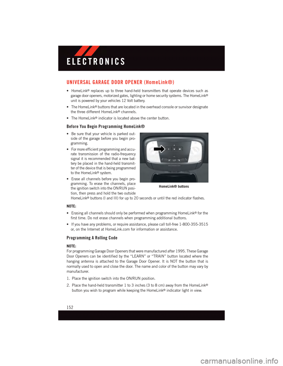
•HomeLink®replaces up to three hand-held transmitters that operate devices such as
garage door openers, motorized gates, lighting or home security systems. The HomeLink®
unit is powered by your vehicles 12 Volt battery.
•TheHomeLink®buttons that are located in the overhead console or sunvisor designate
the three different HomeLink®channels.
•TheHomeLink®indicator is located above the center button.
Before You Begin Programming HomeLink®
•Besurethatyourvehicleisparkedout-
side of the garage before you begin pro-
gramming.
•For more efficient programming and accu-
rate transmission of the radio-frequency
signal it is recommended that a new bat-
tery be placed in the hand-held transmit-
ter of the device that is being programmed
to the HomeLink®system.
•Erase all channels before you begin pro-
gramming. To erase the channels, place
the ignition switch into the ON/RUN posi-
tion, then press and hold the two outside
HomeLink®buttons (I and III) for up to 20 seconds or until the red indicator flashes.
NOTE:
•ErasingallchannelsshouldonlybeperformedwhenprogrammingHomeLink®for the
first time. Do not erase channels when programming additional buttons.
•Ifyouhaveanyproblems,orrequireassistance,pleasecalltoll-free1-800-355-3515
or, on the Internet at HomeLink.com for information or assistance.
Programming A Rolling Code
NOTE:
For programming Garage Door Openers that were manufactured after 1995. These Garage
Door Openers can be identified by the “LEARN” or “TRAIN” button located where the
hanging antenna is attached to the Garage Door Opener. It is NOT the button that is
normally used to open and close the door. The name and color of the button may vary by
manufacturer.
1. Place the ignition switch into the ON/RUN position.
2. Place the hand-held transmitter 1 to 3 inches (3 to 8 cm) away from the HomeLink®
button you wish to program while keeping the HomeLink®indicator light in view.
HomeLink® buttons
ELECTRONICS
152
Page 155 of 236
3. Push and hold the HomeLink®button you want to program while you push and hold
the hand-held transmitter button.
4. Continue to hold both buttons and observe the indicator light. The HomeLink®
indicator will flash slowly and then rapidly after HomeLink®has received the fre-
quency signal from the hand-held transmitter. Release both buttons after the indicator
light changes from slow to rapid.
5. At the garage door opener motor (in the garage), locate the “LEARN” or “TRAINING”
button. This can usually be found where the hanging antenna wire is attached to the
garage door opener motor. Firmly push and release the “LEARN” or “TRAINING”
button.
NOTE:
Yo u h a v e 3 0 s e c o n d s i n w h i c h t o i n i t i a t e t h e n e x t s t e p a f t e r t h e L E A R N b u t t o n h a s b e e n
pushed.
6.Return to the vehicle and push the programmed HomeLink®button twice (holding the
button for two seconds each time). If the device is plugged in and activates, programming
is complete.
NOTE:
If the device does not activate, push the button a third time (for two seconds) to complete
the training.
7.To p r o g r a m t h e r e m a i n i n g t w o H o m e L i n k®buttons, repeat each step for each remaining
button. DO NOT erase the channels.
Programming A Non-Rolling Code
NOTE:
For programming Garage Door Openers manufactured before 1995.
1. Turn the ignition switch to the ON/RUN position.
2. Place the hand-held transmitter 1 to 3 inches (3 to 8 cm) away from the HomeLink®
button you wish to program while keeping the HomeLink®indicator light in view.
3. Push and hold the HomeLink®button you want to program while you push and hold
the hand-held transmitter button.
4.Continue to hold both buttons and observe the indicator light. The HomeLink®indicator
will flash slowly and then rapidly after HomeLink®has received the frequency signal from
the hand-held transmitter. Release both buttons after the indicator light changes from
slow to rapid.
5. Push and hold the programmed HomeLink®button and observe the indicator light.
If the indicator light stays on constantly, programming is complete and the garage door
(or device) should activate when the HomeLink®button is pushed.
6.To p r o g r a m t h e t w o r e m a i n i n g H o m e L i n k®buttons, repeat each step for each remaining
button. DO NOT erase the channels.
ELECTRONICS
153
Page 157 of 236

POWER OUTLET
The front power outlet is located in the front center storage bin of the instrument panel.
There is one power outlet located in the
center console.
The rear power outlet is located in the right
rear cargo area.
The power outlets are labeled with either a
“key” or a “battery” symbol to indicate how
the outlet is powered. Power outlets labeled
with a “key” are powered when the ignition
switch is in the ON/RUN or ACC position,
while the outlets labeled with a “battery”
are connected directly to the battery and
powered at all times.
NOTE:
•Donotexceedthemaximumpowerof
160 Watts (13 Amps) at 12 Volts. If the
160 Watt (13 Amp) power rating is ex-
ceeded, the fuse protecting the system
will need to be replaced. See below im-
age for fuse locations.
•Poweroutletsaredesignedforaccessory
plugs only. Do not insert any other object
in the power outlet as this will damage
the outlet and blow the fuse. Improper use of the power outlet can cause damage not
covered by your new vehicle warranty.
Front Power Outlet
Center Console Outlet
ELECTRONICS
155
Page 160 of 236
Shifting Procedures
AWD Auto To Low Range
NOTE:
When shifting into or out of LOW RANGE some gear noise may be heard. This noise is
normal and is not detrimental to the vehicle or occupants.
•Shiftingcanbeperformedwiththevehiclerolling2to3mph(3to5km/h)or
completely stopped. Use either of the following procedures:
Preferred Procedure
1. With the engine running, slow the vehicle to 2 to 3 mph (3 to 5 km/h).
2. Shift the transmission into NEUTRAL.
3. While still rolling, rotate the transfer case control switch to the desired position.
4. After the desired position indicator light is ON (not flashing), shift the transmission
back into gear.
Alternate Procedure
1. Bring the vehicle to complete stop.
2. With the ignition switch in the ON position and the engine either OFF or running, shift
the transmission into NEUTRAL.
3. Rotate the transfer case control switch to the desired position.
4. After the desired position indicator light is ON (not flashing), shift the transmission
back into gear.
NOTE:
•IfSteps1or2ofeitherthePreferredorAlternateProcedurearenotsatisfiedpriorto
attempting the shift or if they no longer are being met while the shift attempt is in
process, the desired position indicator light will flash continuously while the original
position indicator light is ON, until all requirements have been met.
•TheignitionswitchmustbeintheONpositionforashifttotakeplaceandforthe
position indicator lights to be operable. If the ignition switch is not in the ON position,
then the shift will not take place and no position indicator lights will be on or flashing.
OFF-ROAD CAPABILITIES
158