Page 157 of 236

POWER OUTLET
The front power outlet is located in the front center storage bin of the instrument panel.
There is one power outlet located in the
center console.
The rear power outlet is located in the right
rear cargo area.
The power outlets are labeled with either a
“key” or a “battery” symbol to indicate how
the outlet is powered. Power outlets labeled
with a “key” are powered when the ignition
switch is in the ON/RUN or ACC position,
while the outlets labeled with a “battery”
are connected directly to the battery and
powered at all times.
NOTE:
•Donotexceedthemaximumpowerof
160 Watts (13 Amps) at 12 Volts. If the
160 Watt (13 Amp) power rating is ex-
ceeded, the fuse protecting the system
will need to be replaced. See below im-
age for fuse locations.
•Poweroutletsaredesignedforaccessory
plugs only. Do not insert any other object
in the power outlet as this will damage
the outlet and blow the fuse. Improper use of the power outlet can cause damage not
covered by your new vehicle warranty.
Front Power Outlet
Center Console Outlet
ELECTRONICS
155
Page 158 of 236
•Therearcargopoweroutletcanbeswitchedto“battery”poweredallthetimeby
switching the power outlet right rear quarter panel fuse in the fuse panel.
Rear Quarter Power Outlet Fuse
1—F90–F91Fuse20A
Power Outlet Fuse Locations
1—F104Fuse20AYellowPowerOutletConsoleBin2—F90–F91Fuse20AYellowPowerOutletRightRearQuarterPanel3—F93Fuse20AYellowCigarLighterInstrumentPanel
ELECTRONICS
156
Page 188 of 236

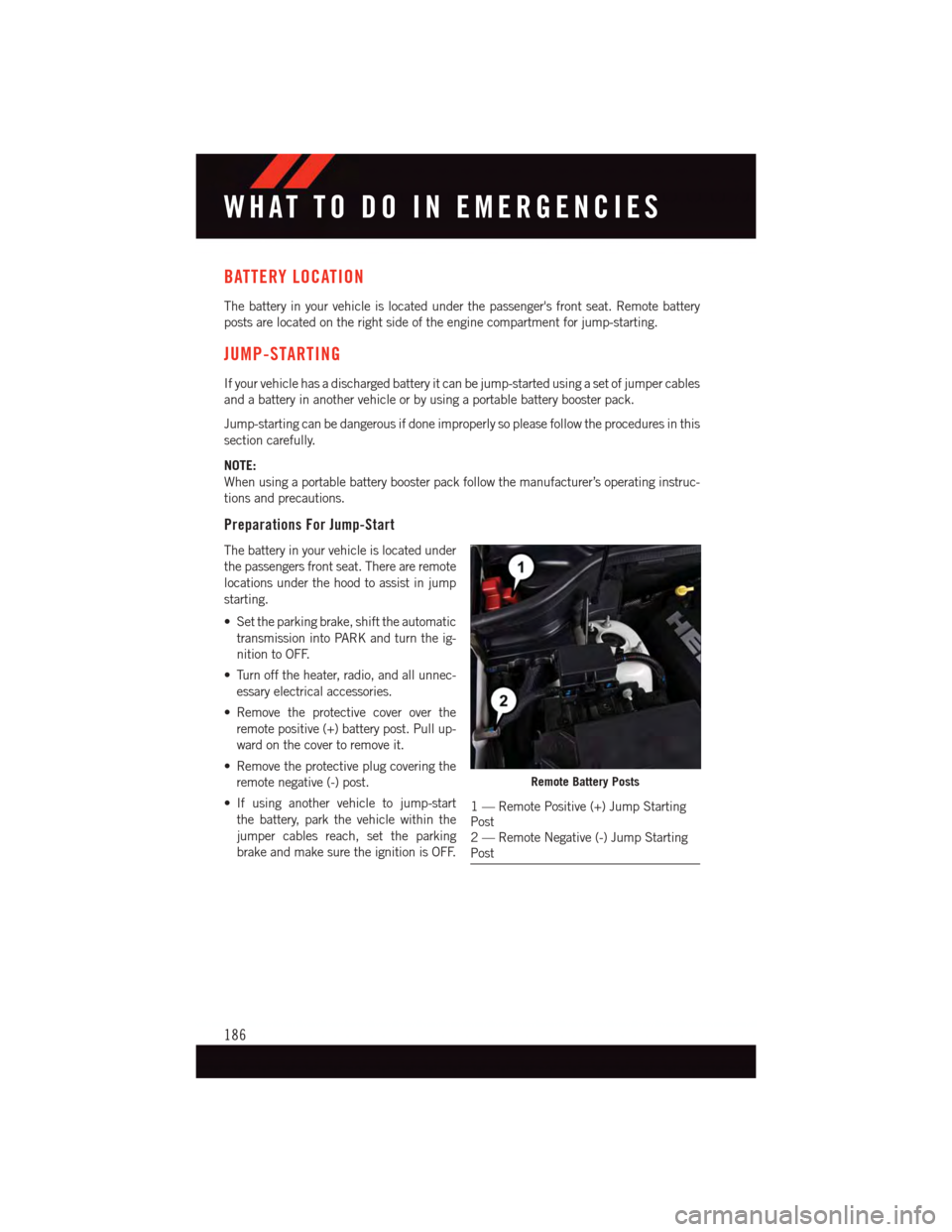
BATTERY LOCATION
The battery in your vehicle is located under the passenger's front seat. Remote battery
posts are located on the right side of the engine compartment for jump-starting.
JUMP-STARTING
If your vehicle has a discharged battery it can be jump-started using a set of jumper cables
and a battery in another vehicle or by using a portable battery booster pack.
Jump-starting can be dangerous if done improperly so please follow the procedures in this
section carefully.
NOTE:
When using a portable battery booster pack follow the manufacturer’s operating instruc-
tions and precautions.
Preparations For Jump-Start
The battery in your vehicle is located under
the passengers front seat. There are remote
locations under the hood to assist in jump
starting.
•Settheparkingbrake,shifttheautomatic
transmission into PARK and turn the ig-
nition to OFF.
•Turnofftheheater,radio,andallunnec-
essary electrical accessories.
•Remove the protective cover over the
remote positive (+) battery post. Pull up-
ward on the cover to remove it.
•Removetheprotectiveplugcoveringthe
remote negative (-) post.
•If using another vehicle to jump-start
the battery, park the vehicle within the
jumper cables reach, set the parking
brake and make sure the ignition is OFF.
Remote Battery Posts
1—RemotePositive(+)JumpStartingPost2—RemoteNegative(-)JumpStartingPost
WHAT TO DO IN EMERGENCIES
186
Page 189 of 236

Jump-Starting Procedure
1. Connect the positive(+)end of the jumper cable to the remote positive(+)post of the
vehicle with discharged battery.
2. Connect the opposite end of the positive(+)jumper cable to the positive(+)post of the
booster battery.
3. Connect the negative(-)end of the jumper cable to the negative(-)post of the booster
battery.
4. Connect the opposite end of the negative(-)jumper cable to the remote negative(-)
post of the vehicle with the discharged battery.
5. Start the engine in the vehicle that has the booster battery, let the engine idle a few
minutes, and then start the engine in the vehicle with the discharged battery.
Once the engine is started, remove the jumper cables in the reverse sequence:
1. Disconnect the negative(-)end of the jumper cable from the remote negative(-)post
of the vehicle with the discharged battery.
2. Disconnect the opposite end of the negative(-)jumper cable from the negative(-)post
of the booster battery.
3. Disconnect the positive(+)end of the jumper cable from the positive(+)post of the
booster battery.
4. Disconnect the opposite end of the positive(+)jumper cable from the remote positive
(+)post of the discharged vehicle.
5. Reinstall the protective cover over the remote positive(+)post of the vehicle with the
discharged battery.
6. Reinstall the protective plug over the remote negative(-)post of the vehicle with the
discharged battery.
NOTE:
If frequent jump-starting is required to start your vehicle you should have the battery and
charging system inspected at your authorized dealer.
CAUTION!
•Donotuseaportablebatteryboosterpackoranyotherboostersourcewithasystem
voltage greater than 12 Volts or damage to the battery, starter motor, alternator or
electrical system may occur.
•Failuretofollowtheseprocedurescouldresultindamagetothechargingsystemof
the booster vehicle or the discharged vehicle.
•Accessoriesthatcanbepluggedintothevehiclepoweroutletsdrawpowerfromthe
vehicle’s battery, even when not in use (e.g., cellular phones, etc.). Eventually, if
plugged in long enough, the vehicle’s battery discharges sufficiently to degrade
battery life and/or prevent the engine from starting.
WHAT TO DO IN EMERGENCIES
187
Page 190 of 236

WARNING!
•Whentemperaturesarebelowthefreezingpoint,electrolyteinadischargedbattery
may freeze. Do not attempt jump-starting because the battery could rupture or
explode and cause personal injury. Battery temperature must be brought above the
freezing point before attempting a jump-start.
•Takecaretoavoidtheradiatorcoolingfanwheneverthehoodisraised.Itcanstart
anytime the ignition switch is on. You can be injured by moving fan blades.
•Removeanymetaljewelry,suchaswatchbandsorbracelets,thatmightmakean
inadvertent electrical contact. You could be severely injured.
•Batteriescontainsulfuricacidthatcanburnyourskinoreyesandgenerate
hydrogen gas which is flammable and explosive. Keep open flames or sparks away
from the battery.
•Donotallowvehiclestotoucheachotherasthiscouldestablishaground
connection and personal injury could result.
•Failuretofollowthisprocedurecouldresultinpersonalinjuryorpropertydamage
due to battery explosion.
•Donotconnectthecabletothenegativepost(-)ofthedischargedbattery.The
resulting electrical spark could cause the battery to explode and could result in
personal injury.
WHAT TO DO IN EMERGENCIES
188
Page 204 of 236
Required Maintenance
Refer to the Maintenance Schedules on the following pages for required maintenance.
At Every Oil Change Interval As Indicated By Oil Change Indicator System:
•Change oil and filter.
•Rotatethetires.Rotate at the first sign of irregular wear, even if it occurs before the oil
indicator system turns on.
•Inspect battery and clean and tighten terminals as required.
•Inspect brake pads, shoes, rotors, drums, hoses and park brake.
•Inspect engine cooling system protection and hoses.
•Inspect exhaust system.
•Inspect engine air cleaner if using in dusty or off-road conditions.
MAINTAINING YOUR VEHICLE
202
Page 208 of 236

FUSES
WARNING!
•Whenreplacingablownfuse,alwaysuseanappropriatereplacementfusewiththe
same amp rating as the original fuse. Never replace a fuse with another fuse of
higher amp rating. Never replace a blown fuse with metal wires or any other
material. Failure to use proper fuses may result in serious personal injury, fire and/or
property damage.
•Beforereplacingafuse,makesurethattheignitionisoffandthatalltheother
services are switched off and/or disengaged.
•Ifthereplacedfuseblowsagain,contactanauthorizeddealer.
•Ifageneralprotectionfuseforsafetysystems(airbagsystem,brakingsystem),
power unit systems (engine system, gearbox system) or steering system blows,
contact an authorized dealer.
Power Distribution Center
The Power Distribution Center is located in the engine compartment near the battery. This
center contains cartridge fuses, micro fuses, relays, and circuit breakers. A description of
each fuse and component may be stamped on the inside cover, otherwise the cavity
number of each fuse is stamped on the inside cover that corresponds to the following
chart.
Cavity Cartridge Fuse Micro FuseDescription
F03 60 Amp Yellow –Radiator Fan
F05 40 Amp Green –Compressor for Air Suspension -If Equipped
F06 40 Amp Green – Anti-lock Brakes/Electronic StabilityControl Pump
F07 40 Amp Green –Starter Solenoid
F08 20 Amp Blue–EmissionSensors(Dieselengineonly)
F09 30 Amp Pink–DieselFuelHeater(Dieselengineonly)
F10 40 Amp Green – Body Controller / Exterior Lighting #2
F11 30 Amp Pink–Tr a i l e r To w E l e c t r i c B r a k e -If Equipped
F12 40 Amp Green –Body Controller #3 / Power Locks
F13 40 Amp Green –Blower Motor Front
F14 40 Amp Green – Body Controller #4 / Interior Lights #2
F17 30 Amp Pink–Headlamp Washer- If Equipped
F19 20 Amp Blue–Headrest Solenoid- If Equipped
F20 30 Amp Pink–Passenger Door Module
F22 20 Amp Blue–Engine Control Module
F23 30 Amp Pink–Interior Lights #1
MAINTAINING YOUR VEHICLE
206
Page 209 of 236

Cavity Cartridge Fuse Micro FuseDescription
F24 30 Amp Pink–Driver Door Module
F25 30 Amp Pink–Front Wipers
F26 30 Amp Pink–Anti-lock Brakes/Stability ControlModule/Valves
F28 20 Amp Blue–Tr a i l e r To w B a c k u p L i g h t s -If Equipped
F29 20 Amp Blue–Tr a i l e r To w P a r k i n g L i g h t s -If Equipped
F30 30 Amp Pink–TrailerTowReceptacle-IfEquipped
F32 30 Amp Pink–Drive Train Control Module
F34 30 Amp Pink–Slip Differential Control
F35 30 Amp Pink–Sunroof - If Equipped
F36 30 Amp Pink–Rear Defroster
F37 25 Amp Clear –Rear Blower Motor - If Equipped
F38 30 Amp Pink–PowerInverter115VAC-IfEquipped
F39 30 Amp Pink–Power Liftgate - If Equipped
F40–10 Amp Red Daytime Running Lights/HeadlampLeveling
F42–20AmpYellowHorn
F44–10 Amp RedDiagnostic Port
F46–10 Amp Red Tire Pressure Monitor - If Equipped
F49–10 Amp Red Integrated Central Stack / ClimateControl
F50–20AmpYellowAirSuspensionControlModule-If Equipped
F51–15 Amp Blue Ignition Node Module / KeylessIgnition / Steering Column Lock
F52–5AmpTanBattery Sensor
F53–20AmpYellowTrailerTow–LeftTurn/StopLights-If Equipped
F55–10 Amp RedDTV / DSRC
F56–15 Amp Blue Additional Content (Diesel engine only)
F57–15 Amp Blue HID Headlamps LH - If Equipped
F59–10 Amp Red Purging Pump (Diesel engine only)
F60–15 Amp Blue Transmission Control Module
F61–10 Amp Red Transmission Control Module/PMSensor (Diesel engine only)
F62–10 Amp Red Air Conditioning Clutch
F63–20AmpYellowIgnition Coils (Gas), Urea Heater (Diesel)
F64–25AmpClearFuelInjectors/Powertrain
F66–10 Amp Red Sunroof / Passenger WindowSwitches / Rain Sensor
MAINTAINING YOUR VEHICLE
207