Page 241 of 638

Using HomeLink®
To operate, push and release the programmed
HomeLink® button. Activation will now occur for the
programmed device (i.e., garage door opener, gate opera-
tor, security system, entry door lock, home/office light-
ing, etc.,). The hand-held transmitter of the device may
also be used at any time.
Security
It is advised to erase all channels before you sell or turn
in your vehicle.
To do this, push and hold the two outside buttons for 20
seconds until the red indicator flashes. Note that all
channels will be erased. Individual channels cannot be
erased.
The HomeLink® Universal Transceiver is disabled when
the Vehicle Security Alarm is active.
Troubleshooting Tips
If you are having trouble programming HomeLink®,
here are some of the most common solutions:
•Replace the battery in the original hand-held transmit-
ter.
•Push the LEARN button on the Garage Door Opener
to complete the training for a Rolling Code.
•Did you unplug the device for programming and
remember to plug it back in?
If you have any problems, or require assistance, please
call toll-free 1-800-355-3515 or, on the Internet at
HomeLink.com for information or assistance.
3
UNDERSTANDING THE FEATURES OF YOUR VEHICLE 239
Page 247 of 638
NOTE:
•All accessories connected to the “battery” powered
outlets should be removed or turned off when the
vehicle is not in use to protect the battery against
discharge.
•To ensure proper cigar lighter operation, a MOPAR®
knob and element must be used.
The front power outlet is located inside the storage area
on the center stack of the instrument panel.
WARNING!
Do not place ashes inside the cubby bin located on
the center console on vehicles not equipped with the
ash receiver tray. A fire leading to bodily injury could
result.
Front Power Outlet
3
UNDERSTANDING THE FEATURES OF YOUR VEHICLE 245
Page 250 of 638
CAUTION!
•Many accessories that can be plugged in draw
power from the vehicle’s battery even when not in
use (i.e., cellular phones, etc.). Eventually, if
plugged in long enough, the vehicle’s battery will
discharge sufficiently to degrade battery life and/or
prevent the engine from starting.
•Accessories that draw higher power (i.e., coolers,
vacuum cleaners, lights, etc.) will degrade the bat-
tery even more quickly. Only use these intermit-
tently and with greater caution.
•After the use of high power draw accessories or
long periods of the vehicle not being started (with
accessories still plugged in), the vehicle must be
driven a sufficient length of time to allow the
alternator to recharge the vehicle’s battery.
(Continued)
CAUTION!(Continued)
•Power outlets are designed for accessory plugs
only. Do not hang any type of accessory or acces-
sory bracket from the plug. Improper use of the
power outlet can cause damage.
248 UNDERSTANDING THE FEATURES OF YOUR VEHICLE
Page 253 of 638
Lighted Cupholders — If Equipped
On some vehicles the rear cupholders are equipped with
a light ring that illuminates the cupholders for the rear
passengers. The light ring is controlled by the Dimmer
Control. Refer to “Lights” in “Understanding The Fea-
tures Of Your Vehicle” for further information.
STORAGE
Glove Compartment
The glove compartment is located on the passenger side
of the instrument panel.
Light Ring In Rear Cupholder
Glove Compartment
3
UNDERSTANDING THE FEATURES OF YOUR VEHICLE 251
Page 262 of 638
INSTRUMENT PANEL FEATURES
1—AirOutlet6—GloveBox2 — Instrument Cluster7 — Power Outlet3—RadioControls—IfEquipped8—IgnitionStart/StopButton4 — Uconnect® System9 — Trunk Release Button5 — Climate Control Hard Controls10 — Headlight Switch
260 UNDERSTANDING YOUR INSTRUMENT PANEL
Page 265 of 638

INSTRUMENT CLUSTER DESCRIPTIONS
1. Tachometer
The red segments indicate the maximum permissible
engine revolutions per minute (RPM x 1000) for each gear
range. Ease up on the accelerator before reaching the red
area. The transition of the red line starts 500 RPM prior to
the actual redline. 6.2L SC redline = 6250 RPM and 6.4L
redline = 6400 RPM.
2. High Beam Indicator
This indicator will turn on when the high beam
headlights are on. Push the multifunction lever
away from the steering wheel to switch the headlights to
high beam.
3. Brake Warning Light
This light monitors various brake functions,
including brake fluid level and parking brake
application. If the brake light turns on, it may
indicate that the parking brake is applied, that the brake
fluid level is low, or that there is a problem with the
anti-lock brake system reservoir.
If the light remains on when the parking brake has been
disengaged, and the fluid level is at the full mark on the
master cylinder reservoir, it indicates a possible brake
hydraulic system malfunction. In this case, the light will
remain on until the condition has been corrected.
The dual brake system provides a reserve braking capac-
ity in the event of a failure to a portion of the hydraulic
system. A leak in either half of the dual brake system is
indicated by the Brake Warning Light which will turn on
when the brake fluid level in the master cylinder has
dropped below a specified level.
The light will remain on until the cause is corrected.
4
UNDERSTANDING YOUR INSTRUMENT PANEL 263
Page 266 of 638

NOTE:The light may flash momentarily during sharp
cornering maneuvers which change fluid level condi-
tions. The vehicle should have service performed, and
the brake fluid level checked.
If brake failure is indicated, immediate repair is neces-
sary.
WARNING!
Driving a vehicle with the brake light on is danger-
ous. Part of the brake system may have failed. It will
take longer to stop the vehicle. You could have a
collision. Have the vehicle checked immediately.
Vehicles equipped with the Anti-Lock Brake System
(ABS) are also equipped with Electronic Brake Force
Distribution (EBD). In the event of an EBD failure, the
Brake Warning Light will turn on along with the ABS
Light. Immediate repair to the ABS system is required.
Operation of the Brake Warning Light can be checked by
placing the ignition from the OFF position to the ON/
RUN position. The light should illuminate for approxi-
mately two seconds. The light should then turn off unless
the parking brake is applied or a brake fault is detected.
If the light does not illuminate, have the light inspected
by an authorized dealer.
The light also will turn on when the parking brake is
applied with the ignition in the ON/RUN position.
NOTE:This light shows only that the parking brake is
applied. It does not show the degree of brake application.
4. Air Bag Warning Light
This light will turn on for four to eight seconds
as a bulb check when the ignition is first cycled
to the ON/RUN position. If the light is either
not on during starting, stays on, or turns on
264 UNDERSTANDING YOUR INSTRUMENT PANEL
Page 268 of 638

6. Park/Headlight ON Indicator
This indicator will illuminate when the park
lights or headlights are turned on.
7. Front Fog Light Indicator — If Equipped
This indicator will illuminate when the front fog
lights are on.
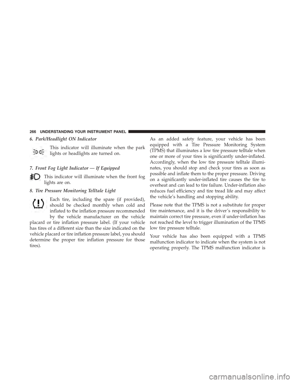
8. Tire Pressure Monitoring Telltale Light
Each tire, including the spare (if provided),
should be checked monthly when cold and
inflated to the inflation pressure recommended
by the vehicle manufacturer on the vehicle
placard or tire inflation pressure label. (If your vehicle
has tires of a different size than the size indicated on the
vehicle placard or tire inflation pressure label, you should
determine the proper tire inflation pressure for those
tires).
As an added safety feature, your vehicle has been
equipped with a Tire Pressure Monitoring System
(TPMS) that illuminates a low tire pressure telltale when
one or more of your tires is significantly under-inflated.
Accordingly, when the low tire pressure telltale illumi-
nates, you should stop and check your tires as soon as
possible and inflate them to the proper pressure. Driving
on a significantly under-inflated tire causes the tire to
overheat and can lead to tire failure. Under-inflation also
reduces fuel efficiency and tire tread life and may affect
the vehicle’s handling and stopping ability.
Please note that the TPMS is not a substitute for proper
tire maintenance, and it is the driver ’s responsibility to
maintain correct tire pressure, even if under-inflation has
not reached the level to trigger illumination of the TPMS
low tire pressure telltale.
Your vehicle has also been equipped with a TPMS
malfunction indicator to indicate when the system is not
operating properly. The TPMS malfunction indicator is
266 UNDERSTANDING YOUR INSTRUMENT PANEL