2015 DODGE CHALLENGER lock
[x] Cancel search: lockPage 157 of 220

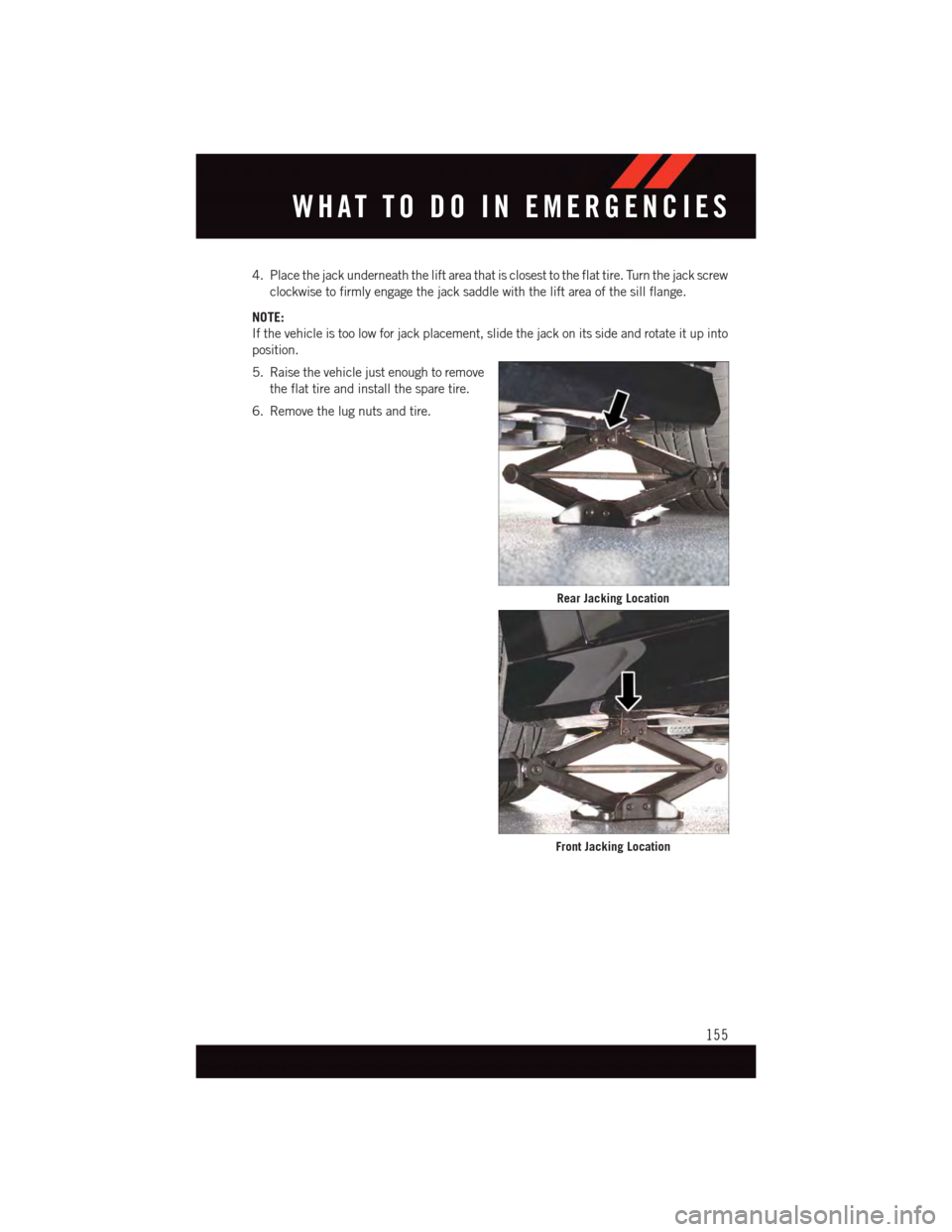
4. Place the jack underneath the lift area that is closest to the flat tire. Turn the jack screw
clockwise to firmly engage the jack saddle with the lift area of the sill flange.
NOTE:
If the vehicle is too low for jack placement, slide the jack on its side and rotate it up into
position.
5. Raise the vehicle just enough to remove
the flat tire and install the spare tire.
6. Remove the lug nuts and tire.
Rear Jacking Location
Front Jacking Location
WHAT TO DO IN EMERGENCIES
155
Page 158 of 220

7. Mount the spare tire.
NOTE:
•Forvehiclessoequipped,donotat-
tempt to install a center cap or wheel
cover on the compact spare.
•Referto“CompactSpareTire”andto
“Limited-Use Spare” under “Tires—
General Information” in “Starting and
Operating” in the Owner's Manual on
the DVD for additional warnings, cau-
tions, and information about the spare
tire, its use, and operation.
8. Install the lug nuts with the cone shaped end of the lug nut toward the wheel. Lightly
tighten the lug nuts.
9. Lower the vehicle to the ground by turning the jack handle counterclockwise.
10. Finish tightening the lug nuts. Push down on the wrench while at the end of the
handle for increased leverage. Tighten the lug nuts in a star pattern until each nut has
been tightened twice. The correct tightness of each lug nut is 130 ft-lb. (176 N·m).
If in doubt about the correct tightness, have them checked with a torque wrench by
your authorized dealer or at a service station.
NOTE:
For the SRT model the correct wheel nut tightness is 111 ft lbs (150 N·m).
11. Stow the jack, tools and flat tire. Make sure the base of the jack faces the front of the
vehicle before tightening down the fastener.
Road Tire Installation
1. Mount the road tire on the axle.
2. Install the remaining lug nuts with the cone shaped end of the nut toward the wheel.
Lightly tighten the lug nuts.
3. Lower the vehicle to the ground by turning the jack handle counterclockwise.
4. Finish tightening the lug nuts. Push down on the wrench while at the end of the handle
for increased leverage. Tighten the lug nuts in a star pattern until each nut has been
tightened twice. The correct tightness of each lug nut is 130 ft-lbs (176 N·m). If in
doubt about the correct tightness, have them checked with a torque wrench by your
authorized dealer or service station.
NOTE:
For the SRT model the correct wheel nut tightness is 111 ft lbs (150 N·m).
5. After 25 miles (40 km) check the lug nut torque with a torque wrench to ensure that
all lug nuts are properly seated against the wheel.
Installing Compact Spare
WHAT TO DO IN EMERGENCIES
156
Page 159 of 220

CAUTION!
Do not attempt to raise the vehicle by jacking on locations other than those indicated
in the Jacking Instructions for this vehicle.
WARNING!
•Donotattempttochangeatireonthesideofthevehicleclosetomovingtraffic.
Pull far enough off the road to avoid the danger of being hit when operating the jack
or changing the wheel.
•Beingunderajacked-upvehicleisdangerous.Thevehiclecouldslipoffthejack
and fall on you. You could be crushed. Never put any part of your body under a
vehicle that is on a jack.
•Neverstartorruntheenginewhilethevehicleisonajack.Ifyouneedtogetunder
araisedvehicle,takeittoaservicecenterwhereitcanberaisedonalift.
•Thejackisdesignedtobeusedasatoolforchangingtiresonly.Thejackshouldnot
be used to lift the vehicle for service purposes. The vehicle should be jacked on a
firm level surface only. Avoid ice or slippery areas.
•Aloosetireorjackthrownforwardinacollisionorhardstopcouldendangertheoccupants
of the vehicle. Always stow the jack parts and the spare tire in the places provided.
•Carefullyfollowthesetirechangingwarningstohelppreventpersonalinjuryor
damage to your vehicle:
•Alwaysparkonafirm,levelsurfaceasfarfromtheedgeoftheroadwayaspossible
before raising the vehicle.
•TurnontheHazardWarningflasher.
•Blockthewheeldiagonallyoppositethewheeltoberaised.
•SettheparkingbrakefirmlyandsetanautomatictransmissioninPARK;amanual
transmission in REVERSE.
•Donotletanyonesitinthevehiclewhenitisonajack.
•Donotgetunderthevehiclewhenitisonajack.
•Only use the jack in the positions indicated and for lifting this vehicle during a tire change.
•Ifworkingonorneararoadway,beextremelycarefulofmotortraffic.
•Raising the vehicle higher than necessary can make the vehicle less stable. It could slip
off the jack and hurt someone near it. Raise the vehicle only enough to remove the tire.
•Toavoidtheriskofforcingthevehicleoffthejack,donotfullytightenthewheel
nuts until the vehicle has been lowered. Failure to follow this warning may result in
personal injury.
•Aloosetireorjackthrownforwardinacollisionorhardstopcouldendangertheoccupants
of the vehicle. Always stow the jack parts and the spare tire in the places provided.
•Thelimited-usesparetiresareforemergencyuseonly.Installationofthislimited-use spare tire affects vehicle handling. With this tire, do not drive more than60 mph (100 km/h). Keep inflated to the cold tire inflation pressure listed on eitheryour tire placard or limited-use spare tire and wheel assembly. Replace (or repair)the original tire at the first opportunity and reinstall it on your vehicle. Failure to doso could result in loss of vehicle control.
WHAT TO DO IN EMERGENCIES
157
Page 164 of 220

5. Remove the Speed Limit sticker from the instrument panel after the tire has been
repaired.
6. Replace the Sealant Bottle (1) and Sealant Hose (6) assembly at your authorized
dealer as soon as possible. Refer to “(F) Sealant Bottle and Hose Replacement.”
NOTE:
•Ifthetirebecomesover-inflated,presstheDeflationButtontoreducethetirepressure
to the recommended inflation pressure before continuing.
•Whenhavingthetireserviced,advisetheauthorizeddealerorservicecenterthatthe
tire has been sealed using the Tire Service Kit.
(F) Sealant Bottle And Hose Replacement:
1. Uncoil the Sealant Hose (6) (clear in color).
2. Locate the round Sealant Bottle release button in the recessed area under the sealant
bottle.
3. Press the Sealant Bottle release button. The Sealant Bottle (1) will pop up. Remove
the bottle and dispose of it accordingly.
4. Clean any remaining sealant from the Tire Service Kit housing.
5. Position the new Sealant Bottle (1) in the housing so that the Sealant Hose (6) aligns
with the hose slot in the front of the housing. Press the bottle into the housing. An
audible click will be heard indicating the bottle is locked into place.
6. Verify that the cap is installed on the fitting at the end of the Sealant Hose (6) and
return the hose to its storage area (located on the bottom of the air pump).
7. Return the Tire Service Kit to its storage location in the vehicle.
NOTE:
•ThemetalendfittingfromPowerPlug(8)maygethotafteruse,soitshouldbehandled
carefully.
•FailuretoreinstallthecaponthefittingattheendoftheSealantHose(6)canresult
in sealant contacting your skin, clothing, and the vehicle’s interior. It can also result in
sealant contacting internal Tire Service Kit components which may cause permanent
damage to the kit.
WHAT TO DO IN EMERGENCIES
162
Page 166 of 220

BATTERY LOCATION
The battery is stored under an access cover in the trunk. Remote battery posts are located
on the right side of the engine compartment for jump-starting.
JUMP-STARTING
•Ifyourvehiclehasadischargedbatteryit
can be jumpstarted using a set of jumper
cables and a battery in another vehicle or
by using a portable battery booster pack.
•Jump-startingcanbedangerousifdone
improperly so please follow the proce-
dures in this section carefully.
NOTE:
When using a portable battery booster pack
follow the manufacturer’s operating instruc-
tions and precautions.
Preparations For Jump-Start
•Thebatteryisstoredunderanaccess
cover in the trunk. Remote battery posts
are located on the right side of the engine
compartment for jump-starting.
NOTE:
The remote battery posts are viewed by standing on the right side of the vehicle looking
over the fender.
•Settheparkingbrake,shifttheautomatictransmissionintoPARKandturntheignition
to LOCK.
•Turnofftheheater,radio,andallunnecessaryelectricalaccessories.
•Ifusinganothervehicletojump-startthebattery,parkthevehiclewithinthejumper
cables reach, set the parking brake and make sure the ignition is OFF.
Jump-Starting Procedure
1. Connect the positive (+) end of the jumper cable to the remote positive (+) post of the
discharged vehicle.
2. Connect the opposite end of the positive (+) jumper cable to the positive (+) post of the
booster battery.
Jump Starting Locations
1—PositiveTerminal2—NegativeTerminal
WHAT TO DO IN EMERGENCIES
164
Page 170 of 220

MANUAL PARK RELEASE — 8 SPEED TRANSMISSION
WARNING!
Always secure your vehicle by fully applying the parking brake, before activating the
Manual Park Release. Activating the Manual Park Release will allow your vehicle to roll
away if it is not secured by the parking brake or by proper connection to a tow vehicle.
Activating the Manual Park Release on an unsecured vehicle could lead to serious
injury or death for those in or around the vehicle.
In order to push or tow the vehicle in cases where the transmission will not shift out of
PA R K ( s u c h a s a d e a d b a t t e r y ) , a M a n u a l P a r k R e l e a s e i s a v a i l a b l e .
Follow these steps to use the Manual Park Release:
1. Firmly apply the parking brake.
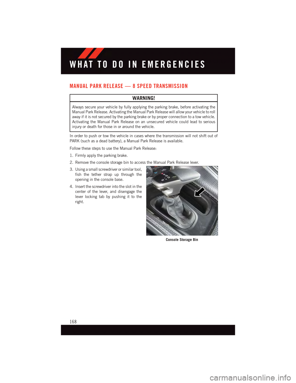
2. Remove the console storage bin to access the Manual Park Release lever.
3. Using a small screwdriver or similar tool,
fish the tether strap up through the
opening in the console base.
4. Insert the screwdriver into the slot in the
center of the lever, and disengage the
lever locking tab by pushing it to the
right.
Console Storage Bin
WHAT TO DO IN EMERGENCIES
168
Page 171 of 220

5. While holding the locking tab in the disengaged position, pull the tether strap to rotate
the lever up and rearward until it locks in place in the vertical position. The vehicle is
now out of PARK and can be towed. Release the parking brake only when the vehicle
is securely connected to a tow vehicle.
To Reset The Manual Park Release:
1. Push the latch (at the base of the lever,
on the rear side) rearward (away from the
lever) to unlatch the lever.
2. Rotate the Manual Park Release lever
forward and down, to its original posi-
tion, until the locking tab snaps into
place to secure the lever.
3. Pull up gently on the tether strap to
confirm that the lever is locked in its
stowed position.
4. Tuck the tether strap into the base of the
console. Reinstall the console storage
bin.
TOWING A DISABLED VEHICLE
This section describes procedures for towing a disabled vehicle using a commercial
towing service.
Towing ConditionWheels OFF TheGroundAUTOMATIC TRANS-MISSIONMANUAL TRANSMIS-SION
Flat TowNONE
If transmission isoperable:•TransmissioninNEUTRAL•30mph(48km/h)maxspeed•30miles(48km)maxdistance
If transmission isoperable:•TransmissioninNEUTRAL•65mph(105 km/h)maxspeed
Wheel Lift or DollyTo w
FrontNOT ALLOWEDNOT RECOM-MENDED
RearNOT RECOM-MENDEDNOT RECOM-MENDED
FlatbedALLBEST METHOD BEST METHOD
Proper towing or lifting equipment is required to prevent damage to your vehicle. Use only
tow bars and other equipment designed for this purpose, following equipment manufac-
turer’s instructions. Use of safety chains is mandatory. Attach a tow bar or other towing
device to main structural members of the vehicle, not to bumpers or associated brackets.
State and local laws regarding vehicles under tow must be observed.
Tether Strap
WHAT TO DO IN EMERGENCIES
169
Page 175 of 220

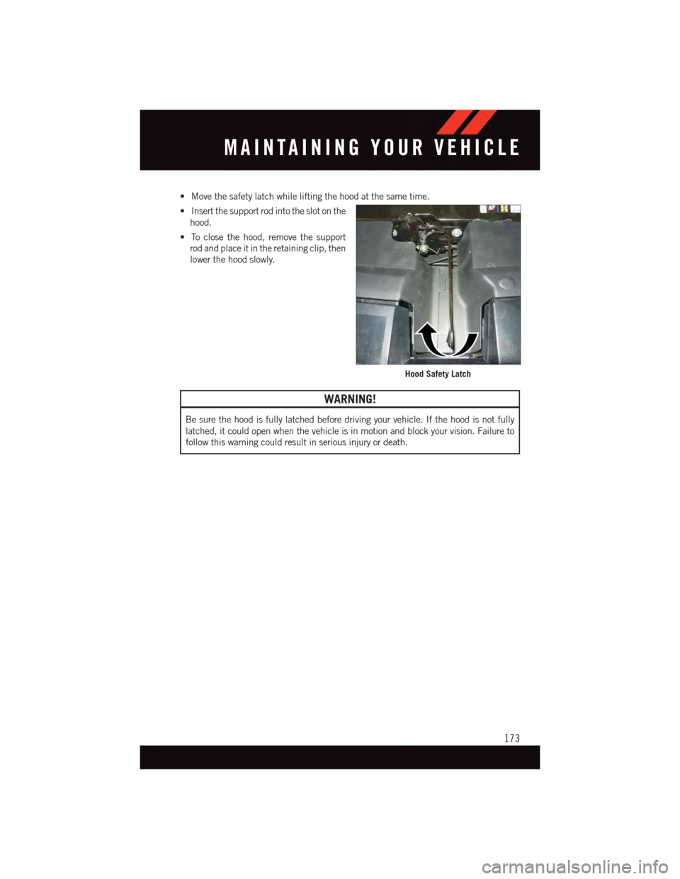
•Movethesafetylatchwhileliftingthehoodatthesametime.
•Insertthesupportrodintotheslotonthe
hood.
•Toclosethehood,removethesupport
rod and place it in the retaining clip, then
lower the hood slowly.
WARNING!
Be sure the hood is fully latched before driving your vehicle. If the hood is not fully
latched, it could open when the vehicle is in motion and block your vision. Failure to
follow this warning could result in serious injury or death.
Hood Safety Latch
MAINTAINING YOUR VEHICLE
173