2015 DODGE CHALLENGER light
[x] Cancel search: lightPage 134 of 220

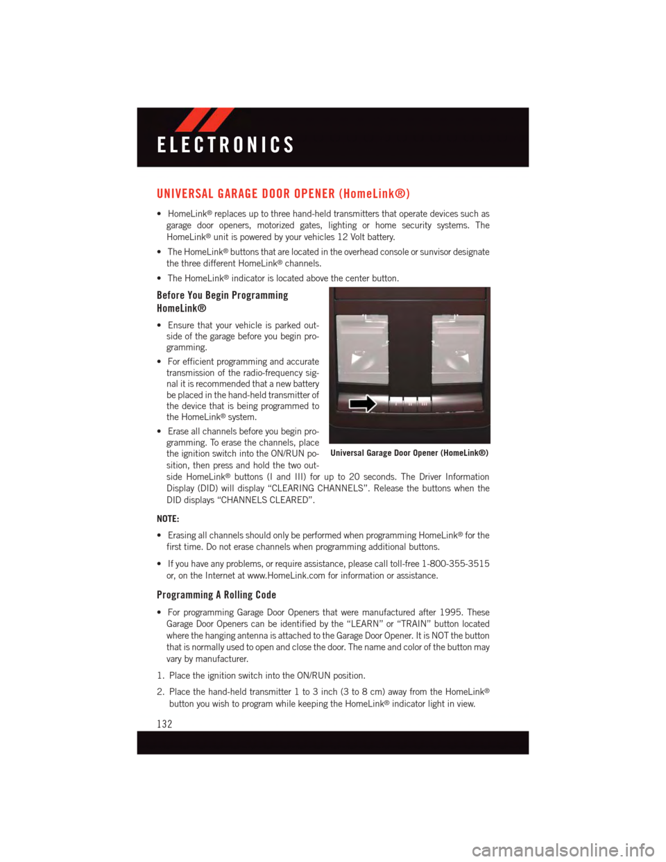
UNIVERSAL GARAGE DOOR OPENER (HomeLink®)
•HomeLink®replaces up to three hand-held transmitters that operate devices such as
garage door openers, motorized gates, lighting or home security systems. The
HomeLink®unit is powered by your vehicles 12 Volt battery.
•TheHomeLink®buttons that are located in the overhead console or sunvisor designate
the three different HomeLink®channels.
•TheHomeLink®indicator is located above the center button.
Before You Begin Programming
HomeLink®
•Ensurethatyourvehicleisparkedout-
side of the garage before you begin pro-
gramming.
•Forefficientprogrammingandaccurate
transmission of the radio-frequency sig-
nal it is recommended that a new battery
be placed in the hand-held transmitter of
the device that is being programmed to
the HomeLink®system.
•Eraseallchannelsbeforeyoubeginpro-
gramming. To erase the channels, place
the ignition switch into the ON/RUN po-
sition, then press and hold the two out-
side HomeLink®buttons (I and III) for up to 20 seconds. The Driver Information
Display (DID) will display “CLEARING CHANNELS”. Release the buttons when the
DID displays “CHANNELS CLEARED”.
NOTE:
•ErasingallchannelsshouldonlybeperformedwhenprogrammingHomeLink®for the
first time. Do not erase channels when programming additional buttons.
•Ifyouhaveanyproblems,orrequireassistance,pleasecalltoll-free1-800-355-3515
or, on the Internet at www.HomeLink.com for information or assistance.
Programming A Rolling Code
•ForprogrammingGarageDoorOpenersthatweremanufacturedafter1995.These
Garage Door Openers can be identified by the “LEARN” or “TRAIN” button located
where the hanging antenna is attached to the Garage Door Opener. It is NOT the button
that is normally used to open and close the door. The name and color of the button may
vary by manufacturer.
1. Place the ignition switch into the ON/RUN position.
2. Place the hand-held transmitter 1 to 3 inch (3 to 8 cm) away from the HomeLink®
button you wish to program while keeping the HomeLink®indicator light in view.
Universal Garage Door Opener (HomeLink®)
ELECTRONICS
132
Page 135 of 220

3. Simultaneously push and hold both the Homelink®button you want to program and
the hand-held transmitter button.
4. Continue to hold buttons until the DID display changes from “CHANNEL # TRAIN-
ING” to “CHANNEL # TRAINED”, then release both buttons.
NOTE:
If the DID displays “DID NOT TRAIN” repeat from Step 2.
5. At the garage door opener motor (in the garage), locate the “LEARN” or “TRAINING”
button. This can usually be found where the hanging antenna wire is attached to the
garage door opener motor. Firmly push and release the “LEARN” or “TRAINING”
button.
NOTE:
Yo u h a v e 3 0 s e c o n d s i n w h i c h t o i n i t i a t e t h e n e x t s t e p a f t e r t h e L E A R N b u t t o n h a s b e e n
pushed.
6. Return to the vehicle and push the programmed HomeLink®button twice (holding the
button for two seconds each time). The DID will display “CHANNEL # TRANSMIT”. If
the garage door opener/device activates, programming is complete.
NOTE:
If the device does not activate, push the button a third time (for two seconds) to complete
the training.
7. To program the remaining two HomeLink®buttons, repeat each step for each
remaining button. DO NOT erase the channels.
Programming A Non-Rolling Code
•ForprogrammingGarageDoorOpenersmanufacturedbefore1995.
1. Turn the ignition switch to the ON/RUN position.
2. Place the hand-held transmitter 1 to 3 inch (3 to 8 cm) away from the HomeLink®
button you wish to program while keeping the HomeLink®indicator light in view.
3. Simultaneously push and hold both the HomeLink®button you want to program and
the hand-held transmitter button.
4. Continue to hold buttons until the DID display changes from “CHANNEL # TRAIN-
ING” to “CHANNEL # TRAINED”, then release both buttons.
5. Push and hold the programmed HomeLink®button and observe the indicator light.
NOTE:
•IftheDIDdisplays“DIDNOTTRAIN”repeatfromStep2.
•ToprogramthetworemainingHomeLink®buttons, repeat each step for each remain-
ing button. DO NOT erase the channels.
ELECTRONICS
133
Page 136 of 220

Using HomeLink®
To o p e r a t e , p u s h a n d r e l e a s e t h e p r o g r a m m e d H o m e L i n k®button. Activation will now
occur for the programmed device (e.g., garage door opener, gate operator, security system,
entry door lock, home/office lighting, etc.). The hand-held transmitter of the device may
also be used at any time.
WARNING!
•Yourmotorizeddoororgatewillopenandclosewhileyouareprogrammingthe
universal transceiver. Do not program the transceiver if people or pets are in the
path of the door or gate.
•Donotrunyourvehicleinaclosedgarageorconfinedareawhileprogrammingthe
transceiver. Exhaust gas from your vehicle contains Carbon Monoxide (CO) which is
odorless and colorless. Carbon Monoxide is poisonous when inhaled and can cause
you and others to be severely injured or killed.
POWER OUTLETS
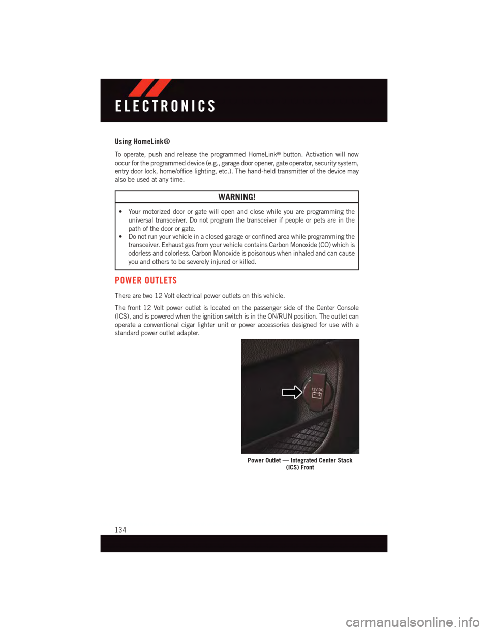
There are two 12 Volt electrical power outlets on this vehicle.
The front 12 Volt power outlet is located on the passenger side of the Center Console
(ICS), and is powered when the ignition switch is in the ON/RUN position. The outlet can
operate a conventional cigar lighter unit or power accessories designed for use with a
standard power outlet adapter.
Power Outlet — Integrated Center Stack(ICS) Front
ELECTRONICS
134
Page 137 of 220

The center console 12 Volt power outlet is powered directly from the battery (power
available at all times). Items plugged into this outlet may discharge the battery and/or
prevent the engine from starting.
NOTE:
•Donotexceedthemaximumpowerof
160 Watts (13 Amps) at 12 Volts. If the
160 Watt (13 Amp) power rating is ex-
ceeded, the fuse protecting the system
will need to be replaced.
•Poweroutletsaredesignedforaccessory
plugs only. Do not insert any other object
in the power outlet as this will damage
the outlet and blow the fuse. Improper
use of the power outlet can cause dam-
age not covered by your new vehicle
warranty.
Power Outlet — Center Console
Power Outlet Fuses
1—#12Fuse20AYellowCigarLighterIntegratedCenterStack2—#38Fuse20AYellowPowerOutletCenterConsole
ELECTRONICS
135
Page 139 of 220

AUTOSTICK
Steering Wheel Mounted Paddle Shifters Or Console Mounted Shifter
AutoStick is a driver-interactive transmission feature providing manual shift control,
giving you more control of the vehicle. AutoStick allows you to maximize engine braking,
eliminate undesirable upshifts and downshifts, and improve overall vehicle performance.
This system can also provide you with more control during passing, city driving, cold
slippery conditions, mountain driving, and many other situations.
Operation
When the shift lever is in the DRIVE (D) position, the transmission will operate automati-
cally, shifting between the eight available gears. To activate AutoStick, move the shift lever
into the MANUAL (M) position (beside the DRIVE position). The current transmission gear
will be displayed in the instrument cluster, along with a highlighted "M" (Manual)
indication. When the shift lever is in the MANUAL (M) position, tap the shift lever forward
(-) (or tap the (-) shift paddle on the steering wheel, if equipped) to downshift the
transmission to the next lower gear, or tap the lever rearward (+) (or tap the (+) shift
paddle, if equipped) to command an upshift.
NOTE:
Ta p p i n g o n e o f t h e s t e e r i n g w h e e l - m o u n t e d s h i f t p a d d l e s ( + / - ) , i f e q u i p p e d , w h i l e t h e s h i f t
lever is in DRIVE, will activate a temporary AutoStick mode. Tapping (-) to enter AutoStick
mode will downshift the transmission to the next lower gear, while using (+) to enter
AutoStick mode will retain the current gear. The current gear will be displayed in the
instrument cluster, but the "M" will not be highlighted. The transmission will revert back
to normal operation (if the shift lever remains in DRIVE) after a period of time, depending
on accelerator pedal activity.
In AutoStick mode, the transmission will shift up or down when (+/-) is manually selected
by the driver (using the shift lever, or the shift paddles [if equipped]), unless an engine
lugging or overspeed condition would result. It will remain in the selected gear until
another upshift or downshift is chosen, except as described below.
•IntemporaryAutoStickmode(shiftleverinDRIVE),thetransmissionwillautomatically
shift up when maximum engine speed is reached. If the accelerator is fully depressed,
the transmission will downshift when possible (based on current vehicle speed and
gear). Lack of accelerator pedal activity will cause the transmission to revert to
automatic operation.
•IfnormalAutoStickmodeisengaged(shiftleverinMANUALposition),manualgear
selection will be maintained until the shift lever is returned to DRIVE, or as described
below. The transmission will not upshift automatically at redline in this mode, nor will
downshifts be obtained if the accelerator pedal is pressed to the floor.
•Thetransmissionwillautomaticallydownshiftasthevehicleslows(topreventengine
lugging) and will display the current gear.
SRT
137
Page 143 of 220

•Engagingtheparkingbrakewilldisablethisfeature.
•Theword“READY”willdisplaywhenconditionsaremetfortheeventtobegin.
•Thedistanceandspeedmeasurementsdisplaywhiletheeventistakingplace.
•Thedistancemeasurementwillbeabortedifthebrakepedalisreleasedbeforethe
vehicle comes to a complete stop.
•ThedistanceandspeedmeasurementswillcontinuetodisplayuntiltheOKbutton is
pushed.
•PushingtheOKbutton will clear the current run and prepare the cluster to record a new
run.
Current G-Force
•Whenselected,thisscreendisplaysthecurrentG-Force(lateralandlongitudinal)along
with a friction circle that displays the directions of the forces.
Peak G-Force
When selected, this screen displays all four G-Force values (two lateral and two longitu-
dinal).
•Whenaforcegreaterthanzeroismeasured,thedisplaywillupdatethevalueasit
climbs. As the G-Force falls, the peak forces will continue to display.
•PushingtheOKbutton will clear the peak force values.
Lap Timer
When selected the Lap Timer page will show the timer always at 0:00.00 with the previous
Best and Last time data (unless the driver has cleared it via hold to Reset).
•PushingOKwillstart“current”timerfrom0:00.0.
•WhenOKispushedthetimesareupdatedaccordingly.
•AssoonasthedriverexitstheLapTimerpagesthe“current”timerwillstopandthe
time will be reset to 0:00.00.
•IfthedriverstaysontheLapTimerpagesthe“current”timerwillresetto0:00.0when
ignition is placed in the off position, or ignition placed in the ON position (or will roll
over at 59:59.99 if ever possible).
•EachtimethedriverpushesOKforaLapthatcurrenttimepopulatestheLasttimeand
also populates the 1st (top) space on the Timer History page the current time resets to
0:00.0 at every push of the OK button.
•Thetimerwillstopwhenthedrivernavigatesawayfromthispage.
Lap History
When selected, this screen displays the Lap History, and will color highlight the time that
is the best time from the Timer Page.
•EachtimethedriverpressestheOKbutton(whileontheLapTimerpage)thecurrent
Lap Time populates the 1st spot and the rest of the data shifts down.
SRT
141
Page 147 of 220

ROADSIDE ASSISTANCE
Dial toll-free 1-800-521-2779 for U.S. Residents or 1-800-363-4869 for Canadian
Residents.
•Provideyourname,vehicleidentificationnumber,licenseplatenumber,andyour
location, including the telephone number from which you are calling.
•Brieflydescribethenatureoftheproblemandanswerafewsimplequestions.
•Youwillbegiventhenameoftheserviceproviderandanestimatedtimeofarrival.If
you feel you are in an “unsafe situation”, please let us know. With your consent, we will
contact local police or safety authorities.
INSTRUMENT CLUSTER WARNING LIGHTS
-LowFuelWarningLight
This warning light indicates when the fuel level reaches approximately 2.0 gal (7.8 L), this
light will turn on and a single chime will sound.
-ElectronicStabilityControl(ESC)Activation/MalfunctionIndicatorLight
The “ESC Activation/Malfunction Indicator Light” in the instrument cluster will come on
when the ignition switch is turned to the ON/RUN position. It should go out with the
engine running. If the “ESC Activation/Malfunction Indicator Light” comes on continu-
ously with the engine running, a malfunction has been detected in the ESC system.
If this light remains on after several ignition cycles, and the vehicle has been driven
several miles (kilometers) at speeds greater than 30 mph (48 km/h), we recommend you
drive to the nearest service center and have the vehicle serviced immediately.
-TirePressureMonitoringSystem(TPMS)Light
Each tire, including the spare (if provided), should be checked monthly when cold and
inflated to the inflation pressure recommended by the vehicle manufacturer on the
vehicle placard or tire inflation pressure label. (If your vehicle has tires of a different size
than the size indicated on the vehicle placard or tire inflation pressure label, you should
determine the proper tire inflation pressure for those tires.)
As an added safety feature, your vehicle has been equipped with a tire pressure
monitoring system (TPMS) that illuminates a low tire pressure telltale when one or more
of your tires is significantly under-inflated. Accordingly, when the low tire pressure telltale
illuminates, you should stop and check your tires as soon as possible, and inflate them to
the proper pressure. Driving on a significantly under-inflated tire causes the tire to
overheat and can lead to tire failure. Under-inflation also reduces fuel efficiency and tire
tread life, and may affect the vehicle’s handling and stopping ability.
WHAT TO DO IN EMERGENCIES
145
Page 148 of 220

IF THE LIGHT STARTS FLASHING INDICATING A LOW TIRE PRESSURE, ADJUST THE AIR
PRESSURE IN THE LOW TIRE TO THE AIR PRESSURE SHOWN ON THE VEHICLE PLACARD OR
TIRE INFLATION PRESSURE LABEL LOCATED ON THE DRIVER'S DOOR.
NOTE:
AFTER INFLATION, THE VEHICLE MAY NEED TO BE DRIVEN FOR 20 MINUTES
BEFORE THE FLASHING LIGHT WILL TURN OFF.
Please note that the TPMS is not a substitute for proper tire maintenance, and it is the
driver’s responsibility to maintain correct tire pressure, even if under-inflation has not
reached the level to trigger illumination of the TPMS low tire pressure telltale.
Yo u r v e h i c l e h a s a l s o b e e n e q u i p p e d w i t h a T P M S m a l f u n c t i o n i n d i c a t o r t o i n d i c a t e w h e n
the system is not operating properly. The TPMS malfunction indicator is combined with
the low tire pressure telltale.
When the system detects a malfunction, the telltale will flash for approximately one
minute and then remain continuously illuminated. This sequence will continue upon
subsequent vehicle start-ups as long as the malfunction exists. When the malfunction
indicator is illuminated, the system may not be able to detect or signal low tire pressure
as intended. TPMS malfunctions may occur for a variety of reasons, including the
installation of replacement or alternate tires or wheels on the vehicle that prevent the
TPMS from functioning properly. Always check the TPMS malfunction telltale after
replacing one or more tires or wheels on your vehicle to ensure that the replacement or
alternate tires and wheels allow the TPMS to continue to function properly.
NOTE:
Ti r e p r e s s u r e s c h a n g e b y a p p r o x i m a t e l y 1 p s i ( 7 k P a ) p e r 1 2 ° F ( 7 ° C ) o f a i r t e m p e r a t u r e
change. Keep this in mind when checking tire pressure inside a garage, especially in the
Winter. Example: If garage temperature is 68°F (20°C) and the outside temperature is
32°F (0°C), then the cold tire inflation pressure should be increased by 3 psi (21 kPa),
which equals 1 psi (7 kPa) for every 12°F (7°C) for this outside temperature condition.
CAUTION!
The TPMS has been optimized for the original equipment tires and wheels. TPMS
pressures and warning have been established for the tire size equipped on your vehicle.
Undesirable system operation or sensor damage may result when using replacement
equipment that is not of the same size, type, and/or style. Aftermarket wheels can
cause sensor damage. Do not use tire sealant from a can, or balance beads if your
vehicle is equipped with a TPMS, as damage to the sensors may result.
WHAT TO DO IN EMERGENCIES
146