Page 514 of 575
CavityCartridge Fuse Mini-FuseDescription
34 —10 Amp Red Steering Column
Module/Clock/Spare –
Police
35 —5 Amp Tan Battery Sensor
36 —15 Amp Blue Electronic Exhaust Valve
– If Equipped
37 —20 Amp Yellow Radio
38 —15 Amp Blue – LD/LX
20 Amp Yellow – LA Console Power Outlet/
Console Media Hub (LD/
LX)
Power Outlet Inside Arm
Rest/Console Media Hub
(LA)
40 ——Fuse — Spare
41 ——Fuse — Spare
42 30 Amp Pink —Rear Defrost
512 MAINTAINING YOUR VEHICLE
Page 566 of 575

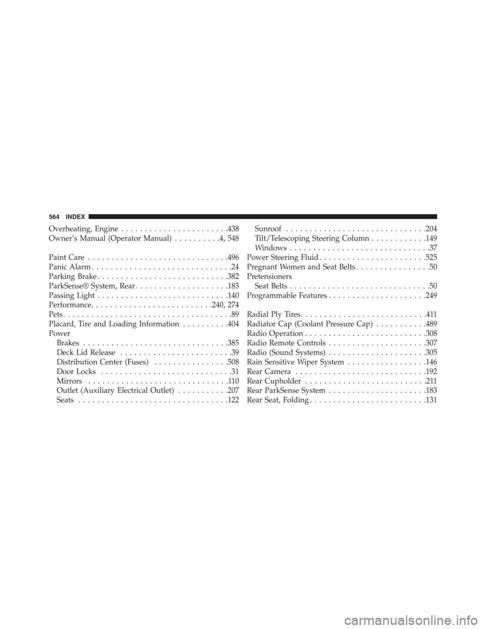
Overheating, Engine...................... .438
Owner’s Manual (Operator Manual) ..........4,548
Paint Care ............................. .496
Panic Alarm ..............................24
Parking Brake ........................... .382
ParkSense® System, Rear ....................183
Passing Light ........................... .140
Performance ......................... .240, 274
Pets ....................................89
Placard, Tire and Loading Information ..........404
Power Brakes .............................. .385
Deck Lid Release ........................39
Distribution Center (Fuses) ................508
Door Locks ............................31
Mirrors ..............................110
Outlet (Auxiliary Electrical Outlet) ...........207
Seats ............................... .122Sunroof
............................. .204
Tilt/Telescoping Steering Column ............149
Windows ..............................37
Power Steering Fluid ...................... .525
Pregnant Women and Seat Belts ................50
Pretensioners Seat Belts ..............................50
Programmable Features .....................249
Radial Ply Tires ...........................411
Radiator Cap (Coolant Pressure Cap) ...........489
Radio Operation ......................... .308
Radio Remote Controls .....................307
Radio (Sound Systems) .....................305
Rain Sensitive Wiper System .................146
Rear Camera ........................... .192
Rear Cupholder ..........................211
Rear ParkSense System .....................183
Rear Seat, Folding ........................ .131
564 INDEX
Page 567 of 575

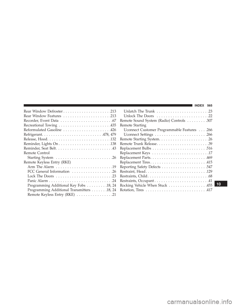
Rear Window Defroster.....................213
Rear Window Features .....................213
Recorder, Event Data .......................67
Recreational Towing ...................... .435
Reformulated Gasoline .....................426
Refrigerant .......................... .478, 479
Release, Hood ........................... .132
Reminder, Lights On ...................... .138
Reminder, Seat Belt .........................43
Remote Control Starting System .........................26
Remote Keyless Entry (RKE) Arm The Alarm .........................19
FCC General Information ..................26
Lock The Doors .........................23
Panic Alarm ............................24
Programming Additional Key Fobs .........18, 24
Programming Additional Transmitters .......18, 24
Remote Keyless Entry (RKE) ................21Unlatch The Trunk
.......................23
Unlock The Doors .......................22
Remote Sound System (Radio) Controls .........307
Remote Starting Uconnect Customer Programmable Features . . . .266
Uconnect Settings ...................... .266
Remote Starting System ......................26
Remote Trunk Release .......................39
Replacement Bulbs ....................... .516
Replacement Keys .........................17
Replacement Parts ........................ .469
Replacement Tires ........................ .415
Reporting Safety Defects ....................547
Restraint, Head .......................... .129
Restraints, Child ...........................68
Restraints, Occupant ........................41
Rocking Vehicle When Stuck .................455
Rotation, Tires .......................... .417
10
INDEX 565
Page 574 of 575

INSTALLATION OF RADIO TRANSMITTING
EQUIPMENT
Special design considerations are incorporated into this
vehicle’s electronic system to provide immunity to radio
frequency signals. Mobile two-way radios and telephone
equipment must be installed properly by trained person-
nel. The following must be observed during installation.
The positive power connection should be made directly
to the battery and fused as close to the battery as possible.
The negative power connection should be made to body
sheet metal adjacent to the negative battery connection.
This connection should not be fused.
Antennas for two-way radios should be mounted on the
roof or the rear area of the vehicle. Care should be used
in mounting antennas with magnet bases. Magnets may
affect the accuracy or operation of the compass on
vehicles so equipped.The antenna cable should be as short as practical and
routed away from the vehicle wiring when possible. Use
only fully shielded coaxial cable.
Carefully match the antenna and cable to the radio to
ensure a low Standing Wave Ratio (SWR).
Mobile radio equipment with output power greater than
normal may require special precautions.
All installations should be checked for possible interfer-
ence between the communications equipment and the
vehicle’s electronic systems.