Page 440 of 575

HAZARD WARNING FLASHERS
The Hazard Warning flasher switch is located in the
switch bank near the bottom center of the instrument
panel.Press the switch to turn on the Hazard Warning
flasher. When the switch is activated, all direc-
tional turn signals will flash on and off to warn oncoming
traffic of an emergency. Press the switch a second time to
turn off the Hazard Warning flashers.
This is an emergency warning system and it should not
be used when the vehicle is in motion. Use it when your
vehicle is disabled and it is creating a safety hazard for
other motorists.
When you must leave the vehicle to seek assistance, the
Hazard Warning flashers will continue to operate even
though the ignition is placed in the OFF position. NOTE:
With extended use the Hazard Warning flashers
may wear down your battery.
IF YOUR ENGINE OVERHEATS
In any of the following situations, you can reduce the
potential for overheating by taking the appropriate ac-
tion.
• On the highways — slow down.
• In city traffic — while stopped, place the transmission
in NEUTRAL, but do not increase engine idle speed.
NOTE: There are steps that you can take to slow down
an impending overheat condition:
• If your air conditioner (A/C) is on, turn it off. The A/C
system adds heat to the engine cooling system and
turning the A/C off can help remove this heat.
• You can also turn the temperature control to maximum
heat, the mode control to floor and the blower control
438 WHAT TO DO IN EMERGENCIES
Page 453 of 575

5. Remove the Speed Limit sticker from the instrumentpanel after the tire has been repaired.
6. Replace the Sealant Bottle (1) and Sealant Hose (6) assembly at your authorized dealer as soon as pos-
sible. Refer to (F) “Sealant Bottle and Hose Replace-
ment”.
NOTE: When having the tire serviced, advise the autho-
rized dealer or service center that the tire has been sealed
using the Tire Service Kit.
(F) Sealant Bottle And Hose Replacement:
1. Uncoil the Sealant Hose (6) (clear in color).
2. Locate the round Sealant Bottle release button in the recessed area under the sealant bottle.
3. Push the Sealant Bottle release button. The Sealant Bottle (1) will pop up. Remove the bottle and dispose
of it accordingly. 4. Clean any remaining sealant from the Tire Service Kit
housing.
5. Position the new Sealant Bottle (1) in the housing so that the Sealant Hose (6) aligns with the hose slot in
the front of the housing. Push the bottle into the
housing. An audible click will be heard indicating the
bottle is locked into place.
6. Verify that the cap is installed on the fitting at the end of the Sealant Hose (6) and return the hose to its
storage area (located on the bottom of the air pump).
7. Return the Tire Service Kit to its storage location in the vehicle.
JUMP-STARTING PROCEDURES
If your vehicle has a discharged battery it can be jump-
started using a set of jumper cables and a battery in
another vehicle or by using a portable battery booster
pack. Jump-starting can be dangerous if done improperly
so please follow the procedures in this section carefully.
6
WHAT TO DO IN EMERGENCIES 451
Page 531 of 575

Your authorized dealer will reset the oil change indicator
message after completing the scheduled oil change. If a
scheduled oil change is performed by someone other
than your authorized dealer, the message can be reset by
referring to the steps described under “Driver Informa-
tion Display (DID)” in “Understanding Your Instrument
Panel” for further information.
At Each Stop For Fuel
•Check the engine oil level. Refer to “Maintenance
Procedures/Engine Oil” in “Maintaining Your Ve-
hicle” for further information.
• Check the windshield washer solvent and add if
required.
Once A Month
• Check tire pressure and look for unusual wear or
damage. •
Inspect the battery, and clean and tighten the terminals
as required.
• Check the fluid levels of the coolant reservoir, brake
master cylinder, and power steering, and add as
needed.
• Check all lights and other electrical items for correct
operation.
At Each Oil Change
• Change the engine oil filter.
• Inspect the brake hoses and lines.
CAUTION!
Failure to perform the required maintenance items
may result in damage to the vehicle.
8
MAINTENANCE SCHEDULES 529
Page 562 of 575

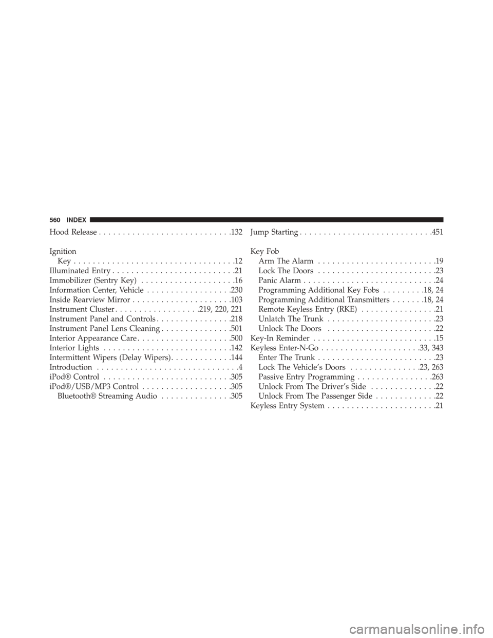
Hood Release........................... .132
Ignition Key..................................12
Illuminated Entry ..........................21
Immobilizer (Sentry Key) ....................16
Information Center, Vehicle ..................230
Inside Rearview Mirror .....................103
Instrument Cluster ..................219, 220, 221
Instrument Panel and Controls ................218
Instrument Panel Lens Cleaning ...............501
Interior Appearance Care ....................500
Interior Lights .......................... .142
Intermittent Wipers (Delay Wipers) .............144
Introduction ..............................4
iPod® Control .......................... .305
iPod®/USB/MP3 Control ...................305
Bluetooth® Streaming Audio ...............305Jump Starting
........................... .451
Key Fob Arm The Alarm .........................19
Lock The Doors .........................23
Panic Alarm ............................24
Programming Additional Key Fobs .........18, 24
Programming Additional Transmitters .......18, 24
Remote Keyless Entry (RKE) ................21
Unlatch The Trunk .......................23
Unlock The Doors .......................22
Key-In Reminder ..........................15
Keyless Enter-N-Go .....................33, 343
Enter The Trunk .........................23
Lock The Vehicle’s Doors ...............23, 263
Passive Entry Programming ................263
Unlock From The Driver’s Side ..............22
Unlock From The Passenger Side .............22
Keyless Entry System .......................21
560 INDEX